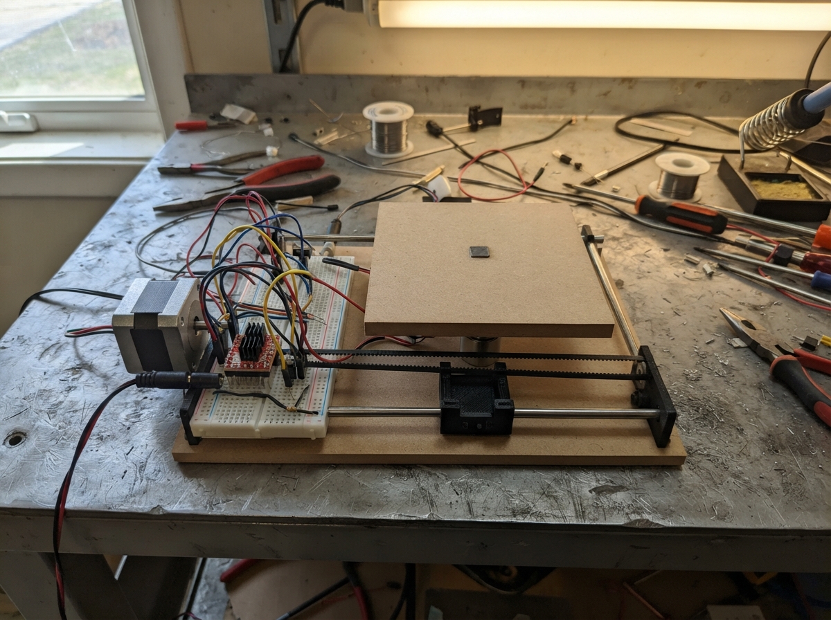
This project builds an automated chess piece mover using stepper motors and a lifting electromagnet to position and retrieve pieces on a chessboard. The system uses three NEMA 17 motors controlled by an ESP32 to move a magnetic head across the X and Y axes and raise or lower it on the Z axis, with home switches ensuring precise calibration.
The guide provides a complete wiring diagram, full parts list, and tested firmware that handles motor control, homing sequences, and magnet activation. Assembly covers building the moving frame, installing the three limit switches, connecting each motor to its A4988 driver, wiring the ESP32 control lines, safely integrating the 5V electromagnet circuit, and testing movement before operation.
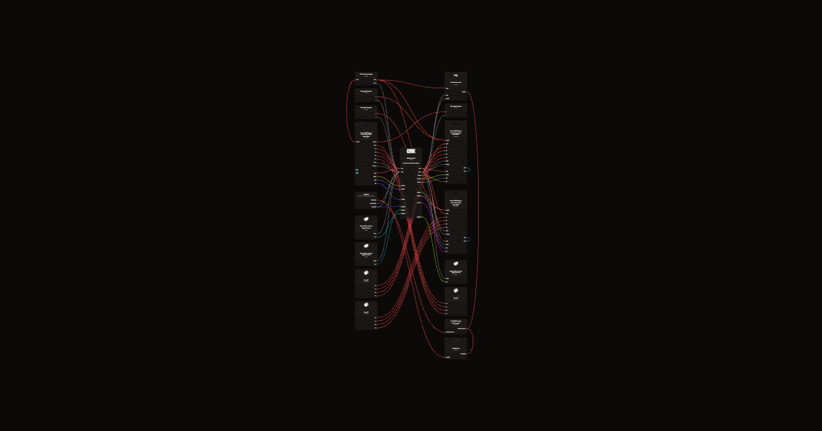
Wiring diagram
Gather all the parts
Assemble it in 7 steps
1. Build the moving frame
Make a rigid 8 by 8 chessboard with 50 mm squares and leave an open space below it. Fit one belt-driven rail left-to-right for X, a second rail front-to-back for Y, and a short vertical lead-screw slide for Z. Mount x_motor, y_motor, and z_motor to their matching axes, and bolt electromagnet to the Z carriage with its flat face pointing down.
- Put the X and Y home corners together at the physical a1 corner; the firmware treats that corner as a1.
- Glue a small flat steel washer into the bottom of every chess piece so the electromagnet has a flat metal surface to grip.
- Keep fingers, loose sleeves, and cables out of the belts and lead screw; the mechanism can pinch them.
2. Fit the three home switches
Screw x_home_switch where the X carriage presses its lever at the a-file edge, y_home_switch where the Y carriage presses at rank 1, and z_home_switch at the safe highest position. Use the COM and NO terminals only: COM goes to GND (ground), and NO goes to GPIO32, GPIO33, or GPIO27 (signal).
- Press each lever by hand: it should make a small click before the carriage hits anything hard.
- Position each switch so it is pressed before the carriage reaches the end stop.
- Do not use the NC terminals in this design; connecting the wrong switch terminal makes the board think it is already at home.
3. Connect each motor to its driver
Place x_driver, y_driver, and z_driver where their heatsinks can get air. Connect each motor's four wires to its own driver: 1A to A+ (motor coil), 1B to A- (motor coil), 2A to B+ (motor coil), and 2B to B- (motor coil). Place x_vmot_cap, y_vmot_cap, and z_vmot_cap directly beside the matching driver, with capacitor + to VMOT (motor power) and capacitor - to GND (ground).
- Find the two wire pairs belonging to each motor coil with a multimeter before connecting them.
- Set each A4988 current-limit adjustment very low first, then raise it only enough that the axis moves without skipping.
- Never plug in or unplug a motor while its A4988 driver has power; that can permanently damage the driver. Do not reverse the capacitor leads; a reversed electrolytic capacitor can burst.
4. Wire the ESP32 control lines
Wire x_driver STEP to GPIO13 (motion pulses), DIR to GPIO14 (direction), and EN to GPIO4 (turns X on). Wire y_driver STEP to GPIO16 (motion pulses), DIR to GPIO17 (direction), and EN to GPIO21 (turns Y on). Wire z_driver STEP to GPIO18 (motion pulses), DIR to GPIO19 (direction), and EN to GPIO22 (turns Z on). On every driver, VDD goes to 3V3 (logic power), both GND pins go to GND (ground), and join RST to SLP then connect SLP to 3V3 (keeps the driver awake).
- Keep the thin ESP32 wires away from the motor wires to reduce electrical noise.
- Leave MS1, MS2, and MS3 unconnected for the safe full-step starting setup; adjust the firmware calibration if you later change the microstep jumpers.
- Do not connect 12 V to an ESP32 pin or to an A4988 VDD pin; both use low-voltage logic and can be damaged.
5. Wire the lifting magnet safely
Connect logic_buck VOUT+ to electromagnet Positive lead (5 V power). Connect the magnet Negative lead to magnet_mosfet Drain, and magnet_mosfet Source to GND (ground). Connect GPIO26 through gate_resistor to the MOSFET Gate, then connect gate_pulldown from that same Gate point to GND. Put flyback_diode directly across the magnet: its striped Cathode goes to the magnet positive wire and its unstriped Anode goes to the magnet negative wire.
- The stripe on the diode identifies the Cathode end.
- Keep the diode physically close to the magnet wires.
- A missing or reversed flyback diode can send a voltage spike into the electronics when the magnet turns off.
6. Connect the power supply
With power unplugged, connect motor_supply +12V to all three A4988 VMOT pins and to logic_buck VIN+. Connect motor_supply GND to every driver GND and to logic_buck VIN-. Adjust the buck converter with a multimeter until VOUT reads exactly 5.0 V, then connect VOUT+ to ESP32 VIN (power) and VOUT- to ESP32 GND (ground).
- Use thicker wire for the 12 V motor wires and keep the three motor-driver grounds joined to the ESP32 ground.
- Plug in the 12 V adapter only after you have checked the buck output with a meter.
- Do not power the ESP32 VIN pin with 12 V; set the buck converter to 5.0 V first or the board can be damaged.
7. Test movement with no chess pieces
Start with the magnet carriage near its top switch and the X/Y carriage near the a1 corner. Power the system, then test homing before fitting pieces. If an axis moves away from its switch during homing, unplug power and reverse that motor's direction by swapping one complete coil pair on its driver.
- Run short moves first and measure the travel of one square; change the calibration values only after the mechanics are repeatable.
- Keep captured pieces out of the travel area; this first build moves normal chess moves and expects captured pieces to be removed by hand.
- Keep hands clear during the first homing run because the carriages move automatically.
Review all connections
1. Connections between "motor_supply" and "ESP32"
2. Connections between "logic_buck" and "ESP32"
3. Connections between "x_vmot_cap" and "ESP32"
4. Connections between "y_vmot_cap" and "ESP32"
5. Connections between "z_vmot_cap" and "ESP32"
6. Connections between "x_driver" and "ESP32"
7. Connections between "y_driver" and "ESP32"
8. Connections between "z_driver" and "ESP32"
9. Connections between "x_home_switch" and "ESP32"
10. Connections between "y_home_switch" and "ESP32"
11. Connections between "z_home_switch" and "ESP32"
12. Connections between "gate_resistor" and "ESP32"
13. Connections between "gate_pulldown" and "ESP32"
14. Connections between "magnet_mosfet" and "ESP32"
15. Connections between "flyback_diode" and "ESP32"
Deploy the firmware
#include <Arduino.h>

// Pin assignments match the wiring diagram.
constexpr int X_STEP_PIN = 13;
constexpr int X_DIR_PIN = 14;
constexpr int Y_STEP_PIN = 16;
constexpr int Y_DIR_PIN = 17;
constexpr int Z_STEP_PIN = 18;
constexpr int Z_DIR_PIN = 19;
constexpr int X_ENABLE_PIN = 4;
constexpr int Y_ENABLE_PIN = 21;
constexpr int Z_ENABLE_PIN = 22;
constexpr int X_HOME_PIN = 32;
constexpr int Y_HOME_PIN = 33;
constexpr int Z_HOME_PIN = 27;
constexpr int MAGNET_PIN = 26;

// Calibration defaults for GT2 belts, 20-tooth pulleys and A4988 drivers at 1/16 microstep.
constexpr long XY_STEPS_PER_SQUARE = 4000;
constexpr long Z_PICKUP_STEPS = 800;
constexpr unsigned int STEP_HALF_PERIOD_US = 500;
constexpr long HOME_MAX_STEPS = 60000;
constexpr long HOME_BACKOFF_STEPS = 200;

struct Axis {
  int stepPin;
  int dirPin;
  int enablePin;
  int homePin;
  long position;
};

Axis xAxis{X_STEP_PIN, X_DIR_PIN, X_ENABLE_PIN, X_HOME_PIN, 0};
Axis yAxis{Y_STEP_PIN, Y_DIR_PIN, Y_ENABLE_PIN, Y_HOME_PIN, 0};
Axis zAxis{Z_STEP_PIN, Z_DIR_PIN, Z_ENABLE_PIN, Z_HOME_PIN, 0};
bool isHomed = false;

void setAxisEnabled(Axis &axis, bool enabled) {
  digitalWrite(axis.enablePin, enabled ? LOW : HIGH); // A4988 EN is active low.
}

void pulse(Axis &axis) {
  digitalWrite(axis.stepPin, HIGH);
  delayMicroseconds(STEP_HALF_PERIOD_US);
  digitalWrite(axis.stepPin, LOW);
  delayMicroseconds(STEP_HALF_PERIOD_US);
}

void moveRelative(Axis &axis, long steps) {
  if (steps == 0) return;
  setAxisEnabled(axis, true);
  digitalWrite(axis.dirPin, steps > 0 ? HIGH : LOW);
  long count = labs(steps);
  for (long i = 0; i < count; ++i) pulse(axis);
  axis.position += steps;
}

bool homeAxis(Axis &axis, const char *name) {
  setAxisEnabled(axis, true);
  // LOW is the assumed direction toward the limit switch. Reverse this only if the mechanism moves away.
  digitalWrite(axis.dirPin, LOW);
  long travelled = 0;
  while (digitalRead(axis.homePin) == HIGH && travelled < HOME_MAX_STEPS) {
    pulse(axis);
    ++travelled;
  }
  if (travelled >= HOME_MAX_STEPS) {
    Serial.printf("ERROR: %s home switch was not reached.\n", name);
    return false;
  }
  // Move away, then approach slowly again so the zero position is repeatable.
  digitalWrite(axis.dirPin, HIGH);
  for (long i = 0; i < HOME_BACKOFF_STEPS; ++i) pulse(axis);
  digitalWrite(axis.dirPin, LOW);
  travelled = 0;
  while (digitalRead(axis.homePin) == HIGH && travelled < HOME_BACKOFF_STEPS * 3) {
    pulse(axis);
    ++travelled;
  }
  if (digitalRead(axis.homePin) == HIGH) {
    Serial.printf("ERROR: %s switch did not close on the second approach.\n", name);
    return false;
  }
  axis.position = 0;
  return true;
}

bool homeAll() {
  digitalWrite(MAGNET_PIN, LOW);
  Serial.println("Homing Z, X, then Y...");
  if (!homeAxis(zAxis, "Z")) return false;
  if (!homeAxis(xAxis, "X")) return false;
  if (!homeAxis(yAxis, "Y")) return false;
  setAxisEnabled(xAxis, false);
  setAxisEnabled(yAxis, false);
  setAxisEnabled(zAxis, false);
  isHomed = true;
  Serial.println("HOME complete: a1 is the lower-left square by the X and Y switches.");
  return true;
}

bool decodeSquare(const String &square, int &file, int &rank) {
  if (square.length() != 2) return false;
  char f = tolower(square.charAt(0));
  char r = square.charAt(1);
  if (f < 'a' || f > 'h' || r < '1' || r > '8') return false;
  file = f - 'a';
  rank = r - '1';
  return true;
}

void moveToSquare(int file, int rank) {
  const long targetX = (long)file * XY_STEPS_PER_SQUARE;
  const long targetY = (long)rank * XY_STEPS_PER_SQUARE;
  moveRelative(xAxis, targetX - xAxis.position);
  moveRelative(yAxis, targetY - yAxis.position);
}

void pickupAndPlace(int fromFile, int fromRank, int toFile, int toRank) {
  moveToSquare(fromFile, fromRank);
  moveRelative(zAxis, Z_PICKUP_STEPS);
  digitalWrite(MAGNET_PIN, HIGH);
  delay(250);
  moveRelative(zAxis, -Z_PICKUP_STEPS);
  moveToSquare(toFile, toRank);
  moveRelative(zAxis, Z_PICKUP_STEPS);
  digitalWrite(MAGNET_PIN, LOW);
  delay(100);
  moveRelative(zAxis, -Z_PICKUP_STEPS);
  setAxisEnabled(xAxis, false);
  setAxisEnabled(yAxis, false);
  setAxisEnabled(zAxis, false);
}

void handleCommand(String command) {
  command.trim();
  command.toUpperCase();
  if (command == "HOME") {
    homeAll();
    return;
  }
  if (!command.startsWith("MOVE ") || command.length() != 9) {
    Serial.println("Use HOME or MOVE e2e4. Captured pieces must be removed by hand in this first build.");
    return;
  }
  String from = command.substring(5, 7);
  String to = command.substring(7, 9);
  int fromFile, fromRank, toFile, toRank;
  if (!decodeSquare(from, fromFile, fromRank) || !decodeSquare(to, toFile, toRank)) {
    Serial.println("ERROR: squares use a1 through h8, for example MOVE e2e4.");
    return;
  }
  if (!isHomed) {
    Serial.println("ERROR: send HOME before moving a piece.");
    return;
  }
  Serial.printf("Moving %s to %s.\n", from.c_str(), to.c_str());
  pickupAndPlace(fromFile, fromRank, toFile, toRank);
  Serial.println("Move complete.");
}

void setup() {
  Serial.begin(115200);
  for (Axis *axis : {&xAxis, &yAxis, &zAxis}) {
    pinMode(axis->stepPin, OUTPUT);
    pinMode(axis->dirPin, OUTPUT);
    pinMode(axis->enablePin, OUTPUT);
    pinMode(axis->homePin, INPUT_PULLUP);
    setAxisEnabled(*axis, false);
  }
  pinMode(MAGNET_PIN, OUTPUT);
  digitalWrite(MAGNET_PIN, LOW);
  Serial.println("Chess gantry ready. Send HOME, then MOVE e2e4.");
}

void loop() {
  if (Serial.available()) {
    String command = Serial.readStringUntil('\n');
    handleCommand(command);
  }
  delay(5);
}
Remix this project
Make it yours in one click
Open a full copy of this project in your own Schematik workspace, diagram, code, parts, and assembly steps included. Swap the sensor, add features, or redesign the whole thing with AI. The author's original stays untouched.