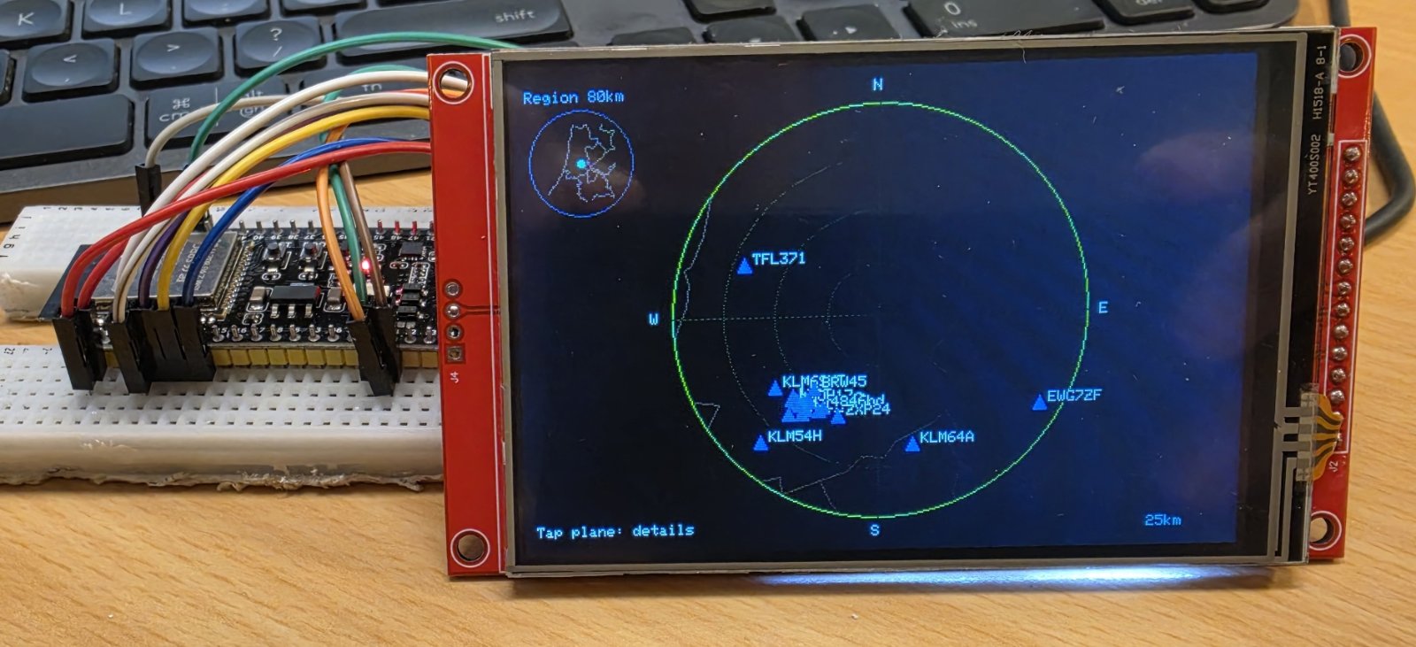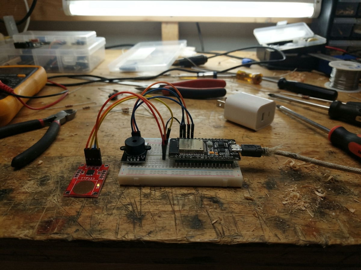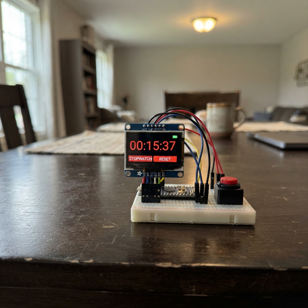
Build a digital stopwatch with a vibrant 1.8 inch color display and two push buttons for control. This ESP32 project displays elapsed time in minutes, seconds, and centiseconds on a bright TFT screen, with the timer turning red while running to provide clear visual feedback.
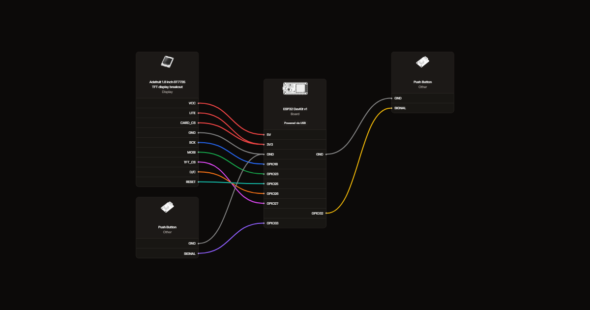
The guide includes a complete wiring diagram showing how to connect the Adafruit ST7735 display and buttons to the ESP32, a full parts list, and ready-to-upload firmware with debounced button handling. Assembly takes just a few minutes—connect the display via SPI, wire up the two buttons to GPIO pins, verify power connections, and upload the code to start timing.
Wiring diagram
Gather all the parts
Assemble it in 3 steps
1. Connect the screen with USB unplugged
Use the Adafruit 1.8-inch ST7735 breakout (product 358). Connect VCC to 5V and GND to GND for power. Connect SCK to GPIO18 (clock), MOSI to GPIO23 (data), TFT_CS to GPIO27 (screen selection), D/C to GPIO26 (data or command), and RESET to GPIO25 (screen reset). Connect LITE to 3V3 (backlight on) and CARD_CS to 3V3 (unused card reader off). Leave MISO unconnected and the card slot empty.
- Use this exact breakout, not a bare display; other modules may not tolerate 5V power.
2. Connect the two buttons
Connect the start/pause button between GPIO32 and GND. Connect the reset button between GPIO33 and GND. For four-leg tactile switches, choose two contacts that connect only when pressed; the two legs on each side are usually already connected.
3. Check power connections
Check each wire against the circuit before connecting USB. Power the ESP32 by USB only. Start/pause turns the digits red while running and white while paused. Reset stops and clears the timer. The display shows minutes, seconds and hundredths and wraps after 99:59.99; unplugging USB clears the time.
Review all connections
1. Connections between "screen" and "ESP32"
2. Connections between "start" and "ESP32"
3. Connections between "reset" and "ESP32"
Deploy the firmware
#include <Arduino.h>
#include <SPI.h>
#include <Adafruit_GFX.h>
#include <Adafruit_ST7735.h>
Adafruit_ST7735 tft(27, 26, 25);
struct Button {
  uint8_t pin; bool raw=true, stable=true; uint32_t changed=0;
  bool pressed(uint32_t now) {
    bool value=digitalRead(pin);
    if(value!=raw){raw=value; changed=now;}
    if(now-changed>=30 && stable!=raw){stable=raw; return !stable;}
    return false;
  }
};
Button startButton{32}, resetButton{33};
bool running=false;
uint64_t elapsed=0;
uint32_t previous=0;
uint64_t lastShown=UINT64_MAX;
bool lastRunning=true;
void setup(){
  pinMode(32, INPUT_PULLUP); pinMode(33, INPUT_PULLUP);
  SPI.begin(18, -1, 23, 27);
  tft.initR(INITR_BLACKTAB); tft.setRotation(1);
  tft.fillScreen(ST77XX_BLACK); tft.setTextWrap(false);
  tft.setTextSize(2); tft.setTextColor(ST77XX_WHITE);
  tft.setCursor(20,10); tft.print("STOPWATCH");
  tft.setTextSize(1); tft.setCursor(14,98); tft.print("START/PAUSE    RESET");
  previous=millis();
}
void loop(){
  uint32_t now=millis();
  if(running) elapsed += uint32_t(now-previous);
  previous=now;
  if(startButton.pressed(now)) running=!running;
  if(resetButton.pressed(now)){elapsed=0; running=false;}
  uint64_t ticks=elapsed/10;
  if(ticks!=lastShown || running!=lastRunning){
    char text[16];
    uint64_t shown=ticks%600000;
    snprintf(text,sizeof(text),"%02u:%02u.%02u",unsigned(shown/6000),unsigned(shown/100%60),unsigned(shown%100));
    tft.setTextSize(3); tft.setTextColor(running?ST77XX_RED:ST77XX_WHITE,ST77XX_BLACK);
    tft.setCursor(8,45); tft.print(text);
    if(running!=lastRunning){
      tft.fillRect(0,78,160,10,ST77XX_BLACK);
      tft.setTextSize(1); tft.setTextColor(ST77XX_WHITE);
      tft.setCursor(56,78); tft.print(running?"RUNNING":"PAUSED");
    }
    lastShown=ticks; lastRunning=running;
  }
  delay(1);
}
Remix this project
Make it yours in one click
Open a full copy of this project in your own Schematik workspace, diagram, code, parts, and assembly steps included. Swap the sensor, add features, or redesign the whole thing with AI. The author's original stays untouched.