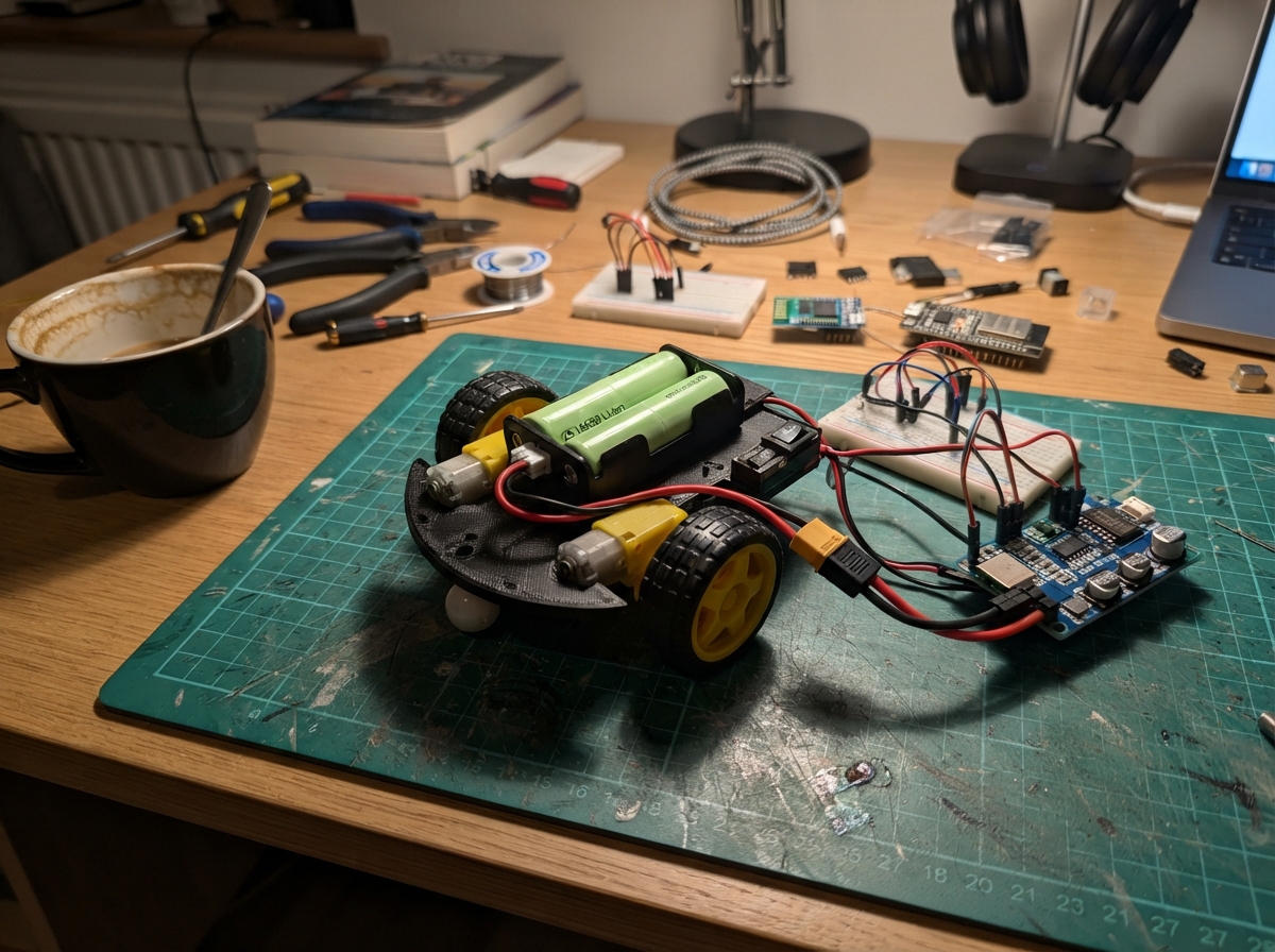
This Bluetooth soccer robot is a fast, agile platform controlled wirelessly via Xbox Series X controller. Built around an ESP32 microcontroller, dual N20 micro metal gear motors, and a DRV8833 motor driver, the robot delivers responsive arcade-style gameplay with real-time battery monitoring and safety features including emergency stop and low-battery cutoff.
This guide provides a complete wiring diagram, full parts list with sourcing notes, pre-configured firmware with Xbox controller support, and step-by-step assembly instructions covering battery preparation, power distribution, motor control setup, and safe first-run testing. Builders will learn how to integrate Bluetooth control, implement dual-motor differential steering, and manage Li-ion power safely with BMS protection and external charging.
Wiring diagram
Gather all the parts
Assemble it in 7 steps
1. Prepare the battery safely
Use two matched genuine 18650 cells with equal charge. The holder must expose its series midpoint. Wire holder BAT- to BMS B-, MID to BM, and BAT+ to B+, following the BMS maker's connection order. Never connect raw cell negative to circuit ground; use protected P- only.
- A shorted lithium battery can cause fire. Do not solder directly to cells. A BMS is not a charger and may not balance cells.
2. Add protected power and charging
Connect BMS P+ through the 5A fuse to XT30 positive and the charging jack center. Connect P- to XT30 negative and jack sleeve. XT30 positive feeds the main switch; negative is circuit ground. Insulate every exposed contact. Use the external 8.4V CC/CV charger only with the main switch OFF.
- Charging remains live with the main switch off. Never charge unattended or while driving. Do not use an ordinary power adapter.
3. Set the two power rails
With ESP32 and drivers disconnected, feed switched positive into both regulator inputs and protected ground into both grounds. Adjust the MP1584 output to 5.0V using a meter; verify the fixed motor regulator outputs 6.0V. Then connect 5V to ESP32 VIN and 6V to both driver VM pins.
- Never connect 8.4V directly to these 6V motors. Disconnect battery power before connecting USB to avoid backfeeding the ESP32 power rail.
4. Fit driver and motor noise capacitors
At each driver connect its 100uF capacitor positive to VM and negative to GND, plus its 100nF ceramic across VM/GND. Solder one 100nF ceramic directly across each motor's terminals, with short leads.
- Reversed electrolytic capacitors can rupture. Keep motor current wiring off solderless breadboards.
5. Connect control and battery sensing
Left driver AIN1/AIN2 go to GPIO16/17 and BIN1/BIN2 to GPIO18/19. Right AIN1/AIN2 go to GPIO21/22 and BIN1/BIN2 to GPIO25/26. Join both nSLEEP pins to GPIO23 and the 1k resistor to ground. Connect switched battery positive through 100k to GPIO34, then 33k and 100nF from GPIO34 to ground. Join all circuit grounds to protected P-.
- At a full 8.4V pack the divider should measure about 2.08V at GPIO34.
6. Connect each independent motor
Left AOUT1/2 feed front-left M+/M-; left BOUT1/2 feed rear-left. Right AOUT1/2 feed front-right; right BOUT1/2 feed rear-right. Keep wires away from moving wheels and insulate connections.
- Verify each motor's 6V stall current is within the actual driver's continuous rating; 10A BMS does not mean drivers can handle 10A. Avoid prolonged stalls.
7. First test with wheels clear
Secure the robot with all wheels off the surface. Follow the firmware test instructions to test FL, RL, FR and RR individually at low speed. Switch off before changing any wiring. Check driver temperature after each short test. Keep the main switch within reach.
- A software brake is not a physical power disconnect. Test controller loss before putting the robot on the floor.
Review all connections
1. Connections between "cell1" and "ESP32"
2. Connections between "cell2" and "ESP32"
3. Connections between "holder" and "ESP32"
4. Connections between "bms" and "ESP32"
5. Connections between "fuse" and "ESP32"
6. Connections between "xt30" and "ESP32"
7. Connections between "charger" and "ESP32"
8. Connections between "switch" and "ESP32"
9. Connections between "logicbuck" and "ESP32"
10. Connections between "motorbuck" and "ESP32"
11. Connections between "left" and "ESP32"
12. Connections between "flnoise" and "ESP32"
13. Connections between "rlnoise" and "ESP32"
14. Connections between "leftbulk" and "ESP32"
15. Connections between "leftbypass" and "ESP32"
16. Connections between "right" and "ESP32"
17. Connections between "frnoise" and "ESP32"
18. Connections between "rrnoise" and "ESP32"
19. Connections between "rightbulk" and "ESP32"
20. Connections between "rightbypass" and "ESP32"
21. Connections between "sleepdown" and "ESP32"
22. Connections between "rtop" and "ESP32"
23. Connections between "rbottom" and "ESP32"
24. Connections between "adcfilter" and "ESP32"
Deploy the firmware
#include <Arduino.h>
#include <XboxSeriesXControllerESP32_asukiaaa.hpp>
#include <math.h>

// Wiring confirmed: shared sleep GPIO23; divider sense GPIO34 (ADC1).
// -1 = normal drive; 0=FL, 1=RL, 2=FR, 3=RR for raised-wheel tests.
constexpr int TEST_MOTOR = -1;
constexpr bool INVERT[4] = {false, false, true, true};
constexpr uint8_t PINS[4][2]={{16,17},{18,19},{21,22},{25,26}};
constexpr uint8_t SLEEP_PIN=23, BATTERY_PIN=34;
constexpr float BATTERY_CAL=1.0f; // Adjust against a voltmeter if needed.
XboxSeriesXControllerESP32_asukiaaa::Core xbox;
struct Input { bool ready=false,b=false,start=false; uint16_t y=32768,x=32768,lt=0,rt=0; uint32_t received=0; };
Input sharedInput;
portMUX_TYPE mux=portMUX_INITIALIZER_UNLOCKED;
volatile bool rumbleRequested=false;
float battery=0,forward=0,turn=0,leftSpeed=0,rightSpeed=0;
bool critical=false,estop=false,armed=false;
uint32_t batteryAt=0,debugAt=0,warningAt=0;

void rumble() {
  XboxSeriesXHIDReportBuilder_asukiaaa::ReportBase r;
  r.v.select.center=true; r.v.select.left=false;
  r.v.select.right=false; r.v.select.shake=false;
  r.v.power.center=35; r.v.timeActive=15;
  r.v.timeSilent=0; r.v.countRepeat=0;
  xbox.writeHIDReport(r);
}
// Bluetooth operations may block during pairing; motor safety runs independently.
void controllerTask(void*) {
  xbox.begin(); bool wasReady=false;
  for (;;) {
    xbox.onLoop();
    Input v;
    v.ready=xbox.isConnected() && !xbox.isWaitingForFirstNotification();
    v.received=xbox.getReceiveNotificationAt();
    if(v.ready) {
      v.y=xbox.xboxNotif.joyLVert; v.x=xbox.xboxNotif.joyRHori;
      v.lt=xbox.xboxNotif.trigLT; v.rt=xbox.xboxNotif.trigRT;
      v.b=xbox.xboxNotif.btnB; v.start=xbox.xboxNotif.btnStart;
    }
    portENTER_CRITICAL(&mux); sharedInput=v; portEXIT_CRITICAL(&mux);
    if(v.ready && (!wasReady || rumbleRequested)) {rumbleRequested=false; rumble();}
    wasReady=v.ready;
    vTaskDelay(pdMS_TO_TICKS(5));
  }
}
void initMotors() {
  pinMode(SLEEP_PIN,OUTPUT); digitalWrite(SLEEP_PIN,LOW);
  for(int m=0;m<4;m++) for(int p=0;p<2;p++) {
    int c=m*2+p; ledcAttachChannel(PINS[m][p],20000,8,c); ledcWriteChannel(c,0);
  }
  digitalWrite(SLEEP_PIN,HIGH); delay(2);
}
void motor(int m,float speed) {
  speed=constrain(speed,-1.0f,1.0f); if(INVERT[m]) speed=-speed;
  int duty=lroundf(fabsf(speed)*255);
  // IN1=IN2=HIGH is active braking. PWM uses slow-decay brake intervals.
  if(speed>0) {ledcWriteChannel(2*m,255); ledcWriteChannel(2*m+1,255-duty);}
  else if(speed<0) {ledcWriteChannel(2*m,255-duty); ledcWriteChannel(2*m+1,255);}
  else {ledcWriteChannel(2*m,255); ledcWriteChannel(2*m+1,255);}
}
void stopMotors() {for(int i=0;i<4;i++) motor(i,0); leftSpeed=rightSpeed=0;}
float stick(uint16_t raw) {
  float v=(float(raw)-32767.5f)/32767.5f;
  if(fabsf(v)<0.10f) return 0;
  return copysignf((fabsf(v)-0.10f)/0.90f,v);
}
void monitorBattery() {
  uint32_t now=millis();
  if(batteryAt && now-batteryAt<1000) return;
  batteryAt=now; uint32_t sum=0;
  for(int i=0;i<16;i++) sum+=analogReadMilliVolts(BATTERY_PIN);
  battery=(sum/16.0f)*0.001f*(133.0f/33.0f)*BATTERY_CAL;
  if(battery<6.2f) critical=true; // latched until power cycle
  if(battery<6.6f && (warningAt==0 || now-warningAt>=10000)) {
    rumbleRequested=true; warningAt=now;
  }
}
void mixDrive(const Input& v) {
  forward=-stick(v.y); turn=stick(v.x);
  float limit=v.lt>100 ? 0.35f : (v.rt>100 ? 1.0f : 0.70f);
  if(battery<6.6f) limit=fminf(limit,0.50f);
  leftSpeed=forward+turn; rightSpeed=forward-turn;
  float scale=fmaxf(1.0f,fmaxf(fabsf(leftSpeed),fabsf(rightSpeed)));
  leftSpeed=leftSpeed/scale*limit; rightSpeed=rightSpeed/scale*limit;
  if(TEST_MOTOR>=0) {
    leftSpeed=rightSpeed=forward*fminf(limit,0.25f);
    for(int i=0;i<4;i++) motor(i,i==TEST_MOTOR ? leftSpeed : 0);
  } else {
    motor(0,leftSpeed); motor(1,leftSpeed); motor(2,rightSpeed); motor(3,rightSpeed);
  }
}
void handleController() {
  Input v; portENTER_CRITICAL(&mux); v=sharedInput; portEXIT_CRITICAL(&mux);
  bool fresh=v.ready && v.received && uint32_t(millis()-v.received)<300;
  if(!fresh) {armed=false; forward=turn=0; stopMotors(); return;}
  forward=-stick(v.y); turn=stick(v.x);
  bool neutral=forward==0 && turn==0 && v.lt<100 && v.rt<100;
  if(v.b) {estop=true; armed=false;}
  if(estop && !v.b && neutral && v.start) estop=false;
  if(!estop && neutral) armed=true;
  if(critical || estop || !armed) {stopMotors(); return;}
  mixDrive(v);
}
void setup() {
  Serial.begin(115200); initMotors(); stopMotors();
  analogReadResolution(12); analogSetPinAttenuation(BATTERY_PIN,ADC_11db);
  monitorBattery();
  xTaskCreatePinnedToCore(controllerTask,"Xbox",8192,nullptr,1,nullptr,0);
  Serial.println("Pair Xbox BLE controller. Center sticks to arm. B stops; neutral + Start resets B stop.");
}
void loop() {
  monitorBattery(); handleController();
  if(millis()-debugAt>=250) {
    debugAt=millis();
    Serial.printf("Y=%.2f X=%.2f L=%.2f R=%.2f battery=%.2fV armed=%d Bstop=%d cutoff=%d test=%d\n",
      forward,turn,leftSpeed,rightSpeed,battery,armed,estop,critical,TEST_MOTOR);
  }
  delay(5);
}
Remix this project
Make it yours in one click
Open a full copy of this project in your own Schematik workspace, diagram, code, parts, and assembly steps included. Swap the sensor, add features, or redesign the whole thing with AI. The author's original stays untouched.