Community project
Ai-thinker-exp32-cam With Ili9341 Only Batt Powe
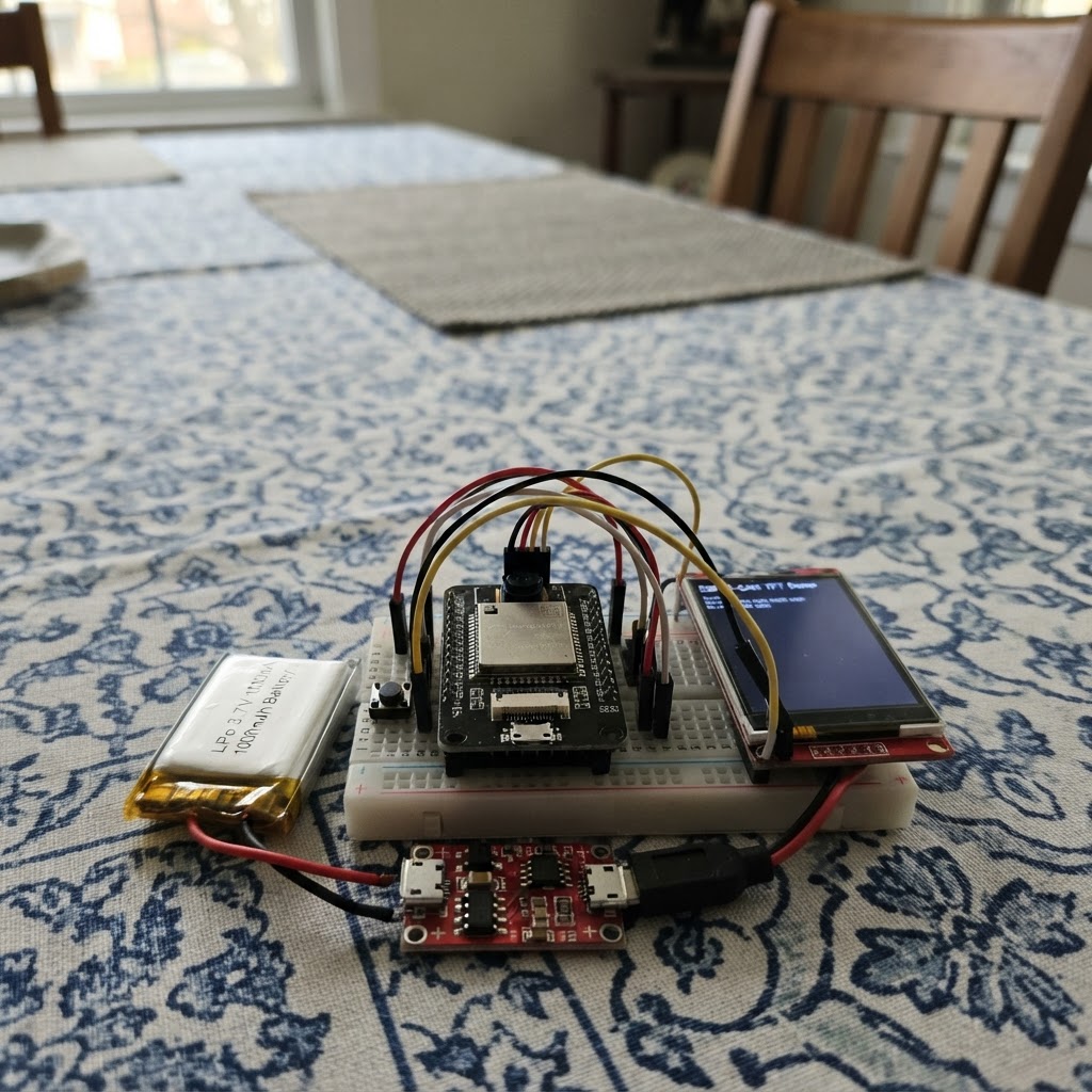
This project builds a battery-powered display controller around the ESP32 platform, using an ILI9341 TFT screen as the primary interface. The system integrates a LiPo battery with charging and protection circuitry, a boost converter for stable 5V supply, and a push button for interactive control. Builders will receive a complete wiring diagram, parts list, step-by-step assembly instructions, and firmware that manages power delivery, display rendering, and user input handling.
The firmware demonstrates SPI communication with the ILI9341 display, button debouncing logic, and display inversion toggling. This guide is ideal for makers looking to create a portable, battery-operated display project with proper power management and a responsive user interface.
Wiring diagram

Gather all the parts
Assemble it in 6 steps
1. Connect the protected battery charger
With every power source disconnected, connect lipo_1 positive (+V) to charger_1 B+ and lipo_1 negative (GND) to charger_1 B-. Use a TP4056 module with separate OUT+/OUT- pads, not a four-pad charger-only board.
- Check the battery connector polarity before soldering.
- Insulate all battery solder joints.
- A LiPo battery can be damaged or become hazardous if reversed or short-circuited.
- Do not connect the ESP32-CAM directly to the battery.
2. Set up the 5 V boost supply
Connect charger_1 OUT+ to boost_1 VIN+ and charger_1 OUT- to boost_1 VIN-. Power the charger from its 5 V USB input and, before attaching the ESP32-CAM, adjust or verify boost_1 is exactly 5.0 V. Then connect boost_1 VOUT+ to the ESP32-CAM 5V/VIN pin and boost_1 VOUT- to an ESP32-CAM GND pin.
- Use a multimeter to check the boost output.
- Choose a boost module rated for at least 1 A peak current.
- Never adjust the boost converter with the ESP32-CAM connected.
- Do not use the ESP32-CAM 3.3 V pin as a 5 V input.
3. Connect TFT power
Connect ili9341_1 VCC and TFT_BL (sometimes labelled LED) to the ESP32-CAM 3.3V pin. Connect ili9341_1 GND to ESP32-CAM GND.
- The ESP32-CAM, display, charger, and boost supply must share ground.
- Keep the display supply wires short.
- Use a 3.3 V logic ILI9341 module. Do not apply the boost converter's 5 V output to display logic pins.
4. Wire the display-only SPI signals
Connect ili9341_1 MOSI to ESP32-CAM GPIO13, SCK to GPIO14, TFT_CS to GPIO15, TFT_DC to GPIO2, and TFT_RST to GPIO4. Leave the ILI9341 MISO and any touchscreen pins unconnected; this project uses only the display. Do not install or use a microSD card because these header pins are shared with the ESP32-CAM microSD interface.
- Keep SPI leads short to reduce display noise.
- The ILI9341 module may label MOSI as SDI or DIN, and SCK as CLK.
- GPIO2 and GPIO15 are boot-strapping pins. Do not add pull-up or pull-down resistors to them.
- If external wiring prevents booting, disconnect TFT power while entering programming mode, then restore it after reset.
5. Add the display-invert button
Connect one terminal of invert_button_1 to ESP32-CAM GPIO12 and the other terminal to GND. The firmware enables the ESP32’s internal pull-up, so no external resistor is needed. A press pulls GPIO12 low and toggles inverted display colors; the display line changes between “Button: invert OFF” and “Button: invert ON.”
- Use the two terminals that are disconnected until the button is pressed; on a four-leg tactile switch these are usually opposite sides.
- Keep the button wiring short.
- GPIO12 is a boot-strap pin. Do not add an external pull-up resistor and do not hold the button while resetting or powering the ESP32-CAM.
- If the board fails to boot, release the button and power-cycle it.
6. Charge and run the unit
Charge through charger_1's USB input only. The display will show the OV2640 camera status and count a test capture every 10 seconds; captures are checked and released immediately, not saved because microSD is unused. Press invert_button_1 briefly to invert or restore the TFT colors.
- Secure the battery away from sharp joints and the camera lens.
- Use Schematik’s Deploy button to flash the project.
- Do not leave a LiPo battery unattended while charging.
- A weak boost converter or thin power wiring can cause ESP32-CAM brownouts during camera captures.
Review all connections
1. Connections between "ili9341_1" and "ESP32"
2. Connections between "lipo_1" and "ESP32"
3. Connections between "charger_1" and "ESP32"
4. Connections between "boost_1" and "ESP32"
5. Connections between "invert_button_1" and "ESP32"
Deploy the firmware
#include <Arduino.h>
#include <SPI.h>
#include <Adafruit_GFX.h>
#include <Adafruit_ILI9341.h>
#include "esp_camera.h"


// Forward declarations
void showInvertState();

bool initCamera();
void drawStaticScreen();
void updateStatus();
void captureAndCount();

constexpr int TFT_MOSI = 13;
constexpr int TFT_SCK = 14;
constexpr int TFT_CS = 15;
constexpr int TFT_DC = 2;
constexpr int TFT_RST = 4;
constexpr int INVERT_BUTTON_PIN = 12;
constexpr uint32_t CAPTURE_INTERVAL_MS = 10000;
constexpr uint32_t BUTTON_DEBOUNCE_MS = 35;
// RGB565 dark gray, equivalent to approximately RGB(123, 125, 123).
constexpr uint16_t COLOR_DARK_GRAY = 0x7BEF;

// Use the portable hardware-SPI constructor; SPI.begin() below supplies the ESP32-CAM pin routing.
Adafruit_ILI9341 tft(TFT_CS, TFT_DC, TFT_RST);
bool cameraReady = false;
uint32_t lastCaptureAt = 0;
uint32_t captureCount = 0;
uint32_t failedCaptures = 0;
bool displayInverted = false;
bool lastButtonReading = HIGH;
bool stableButtonState = HIGH;
uint32_t lastButtonChangeAt = 0;

bool initCamera() {
  camera_config_t config = {};
  config.ledc_channel = LEDC_CHANNEL_0;
  config.ledc_timer = LEDC_TIMER_0;
  config.pin_d0 = 5;
  config.pin_d1 = 18;
  config.pin_d2 = 19;
  config.pin_d3 = 21;
  config.pin_d4 = 36;
  config.pin_d5 = 39;
  config.pin_d6 = 34;
  config.pin_d7 = 35;
  config.pin_xclk = 0;
  config.pin_pclk = 22;
  config.pin_vsync = 25;
  config.pin_href = 23;
  config.pin_sccb_sda = 26;
  config.pin_sccb_scl = 27;
  config.pin_pwdn = 32;
  config.pin_reset = -1;
  config.xclk_freq_hz = 20000000;
  config.pixel_format = PIXFORMAT_JPEG;
  config.frame_size = FRAMESIZE_QVGA;
  config.jpeg_quality = 12;
  config.fb_count = 1;
  config.grab_mode = CAMERA_GRAB_WHEN_EMPTY;
  return esp_camera_init(&config) == ESP_OK;
}

void drawStaticScreen() {
  tft.fillScreen(ILI9341_BLACK);
  tft.setTextWrap(false);
  tft.setTextColor(ILI9341_CYAN, ILI9341_BLACK);
  tft.setTextSize(2);
  tft.setCursor(12, 12);
  tft.print("ESP32-CAM");

  tft.setTextColor(ILI9341_WHITE, ILI9341_BLACK);
  tft.setTextSize(1);
  tft.setCursor(12, 45);
  tft.print("OV2640 capture monitor");
  tft.drawFastHLine(12, 62, 216, COLOR_DARK_GRAY);
  tft.setCursor(12, 80);
  tft.print("Camera:");
  tft.setCursor(12, 112);
  tft.print("Captures:");
  tft.setCursor(12, 144);
  tft.print("Failures:");
  tft.setTextColor(ILI9341_YELLOW, ILI9341_BLACK);
  tft.setCursor(12, 192);
  tft.print("microSD not used");
  tft.setTextColor(ILI9341_WHITE, ILI9341_BLACK);
  tft.setCursor(12, 216);
  tft.print("Button: invert OFF");
}

void updateStatus() {
  tft.fillRect(95, 76, 125, 18, ILI9341_BLACK);
  tft.setCursor(95, 80);
  tft.setTextSize(2);
  tft.setTextColor(cameraReady ? ILI9341_GREEN : ILI9341_RED, ILI9341_BLACK);
  tft.print(cameraReady ? "READY" : "ERROR");

  tft.fillRect(95, 108, 125, 18, ILI9341_BLACK);
  tft.setCursor(95, 112);
  tft.setTextColor(ILI9341_WHITE, ILI9341_BLACK);
  tft.print(captureCount);

  tft.fillRect(95, 140, 125, 18, ILI9341_BLACK);
  tft.setCursor(95, 144);
  tft.setTextColor(failedCaptures ? ILI9341_RED : ILI9341_WHITE, ILI9341_BLACK);
  tft.print(failedCaptures);
}

void showInvertState() {
  tft.fillRect(12, 212, 216, 14, ILI9341_BLACK);
  tft.setTextSize(1);
  tft.setTextColor(ILI9341_WHITE, ILI9341_BLACK);
  tft.setCursor(12, 216);
  tft.print("Button: invert ");
  tft.print(displayInverted ? "ON" : "OFF");
}

void captureAndCount() {
  if (!cameraReady) return;
  camera_fb_t *frame = esp_camera_fb_get();
  if (frame != nullptr) {
    ++captureCount;
    esp_camera_fb_return(frame);
  } else {
    ++failedCaptures;
  }
  updateStatus();
}

void setup() {
  Serial.begin(115200);
  pinMode(INVERT_BUTTON_PIN, INPUT_PULLUP);
  SPI.begin(TFT_SCK, -1, TFT_MOSI, TFT_CS);
  tft.begin(40000000);
  tft.setRotation(1);
  drawStaticScreen();

  cameraReady = initCamera();
  updateStatus();
  if (cameraReady) captureAndCount();
  lastCaptureAt = millis();
}

void loop() {
  const uint32_t now = millis();
  const bool buttonReading = digitalRead(INVERT_BUTTON_PIN);
  if (buttonReading != lastButtonReading) {
    lastButtonChangeAt = now;
    lastButtonReading = buttonReading;
  }
  if (now - lastButtonChangeAt >= BUTTON_DEBOUNCE_MS && buttonReading != stableButtonState) {
    stableButtonState = buttonReading;
    if (stableButtonState == LOW) {
      displayInverted = !displayInverted;
      tft.invertDisplay(displayInverted);
      showInvertState();
    }
  }

  if (now - lastCaptureAt >= CAPTURE_INTERVAL_MS) {
    lastCaptureAt = now;
    captureAndCount();
  }
}
Remix this project
Make it yours in one click
Open a full copy of this project in your own Schematik workspace — diagram, code, parts, and assembly steps included. Swap the sensor, add features, or redesign the whole thing with AI. The author's original stays untouched.