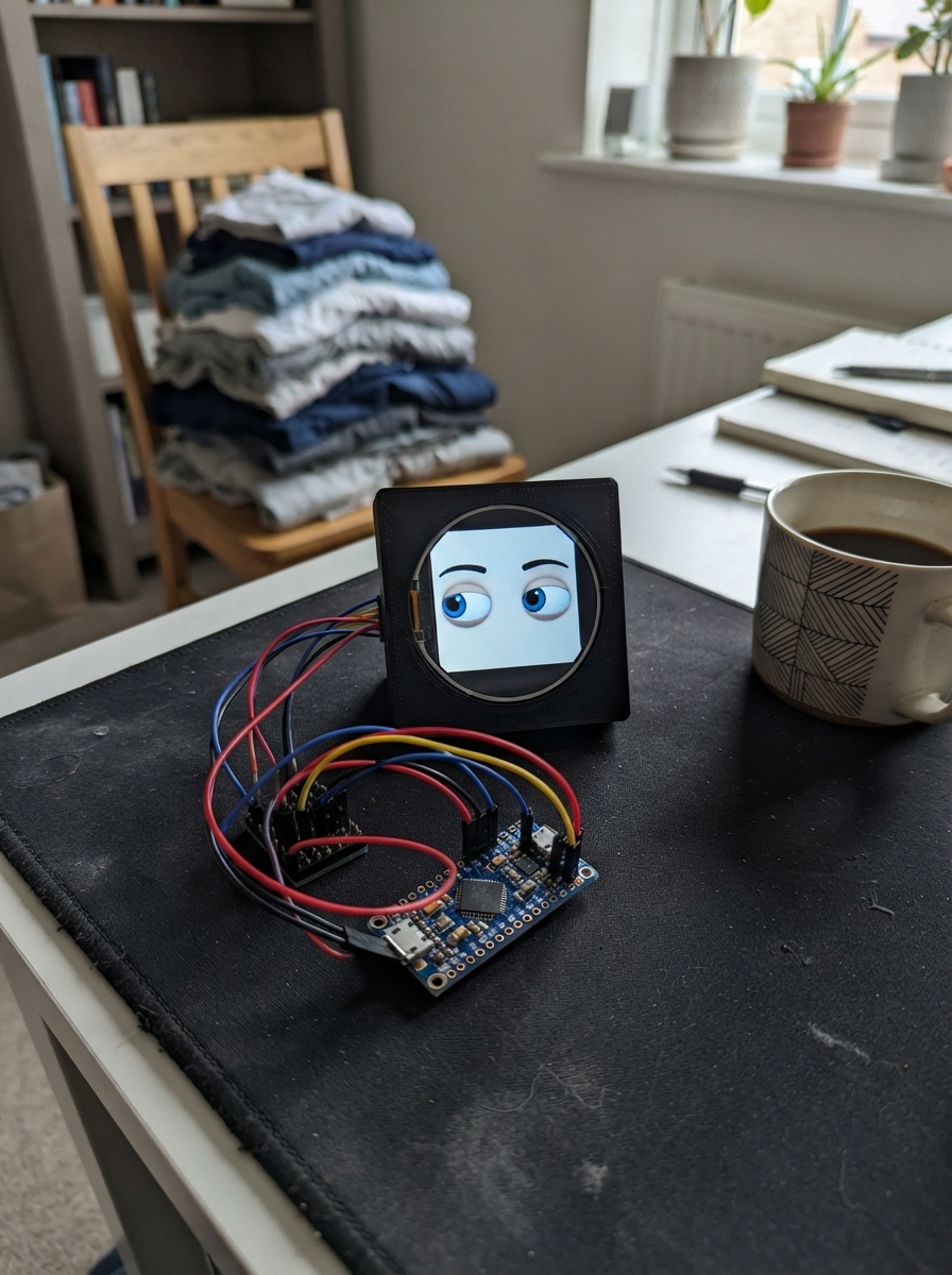
This project brings a pair of animated eyes to life using two round 1.28-inch GC9A01 displays driven by a single ESP32. The eyes track a moving gaze point, blink at random intervals, and render expressive eyelids—perfect for robots, masks, or interactive art installations that need character and presence.
The guide provides a complete wiring diagram showing how to connect both displays to the ESP32 via a shared SPI bus with independent chip select and DC lines, a full parts list, and step-by-step assembly instructions. The included firmware renders smooth animations from a shared framebuffer, handles gaze tracking with easing, and manages blinking behavior—everything needed to get expressive eyes up and running.
Wiring diagram
Gather all the parts
Assemble it in 5 steps
1. Préparer les deux écrans
Utiliser deux modules ronds TFT 1,28 pouce 240 × 240 à contrôleur GC9A01/GC9A01A. Débrancher le câble USB avant le câblage. Placer les écrans côte à côte.
- Ce branchement ne convient pas à un écran avec un autre contrôleur ou à une dalle nue sans module.
2. Brancher l’alimentation
Sur chaque écran, relier VCC au 3V3, GND au GND et BL (ou BLK) au 3V3 pour allumer le rétroéclairage du module. Les deux écrans partagent ces alimentations.
- Ne pas relier les signaux à 5 V. Vérifier les noms des broches, pas leur position sur le connecteur.
3. Brancher les signaux communs
Sur les deux écrans, SCK (aussi marqué CLK ou SCL) va à GPIO4 pour l’horloge ; MOSI (SDA ou DIN) va à GPIO6 pour les données. Ces écrans utilisent SPI : SDA/SCL ne signifient pas ici I2C.
- Utiliser des fils courts, idéalement moins de 15 cm.
4. Distinguer les deux yeux
DC va à GPIO3 sur l’écran gauche et à GPIO5 sur l’écran droit (choix commandes ou image). Écran gauche : CS vers GPIO7 (sélection), RST ou RES vers GPIO1 (remise à zéro). Écran droit : CS vers GPIO10, RST ou RES vers GPIO0. Aucun fil MISO n’est nécessaire.
5. Vérifier avant de brancher
Vérifier chaque liaison et l’absence de court-circuit entre 3V3 et GND. Alimenter ensuite la SuperMini par USB. Les deux yeux bleus regardent ensemble et clignent automatiquement.
- Si la carte redémarre ou chauffe, débrancher immédiatement et vérifier le câblage et la consommation des modules : la capacité du régulateur 3,3 V varie selon les SuperMini.
Review all connections
1. Connections between "gauche" and "ESP32"
2. Connections between "droite" and "ESP32"
Deploy the firmware
#include <Arduino.h>
#include <SPI.h>
#include <math.h>
#include <Adafruit_GFX.h>
#include <Adafruit_GC9A01A.h>

constexpr int SCK_PIN=4, MOSI_PIN=6, DC_PIN=3, RIGHT_DC=5;
constexpr int LEFT_CS=7, RIGHT_CS=10, LEFT_RST=1, RIGHT_RST=0;
Adafruit_GC9A01A leftEye(&SPI, DC_PIN, LEFT_CS, LEFT_RST);
Adafruit_GC9A01A rightEye(&SPI, RIGHT_DC, RIGHT_CS, RIGHT_RST);
GFXcanvas16 image(240,240); // One shared framebuffer: 115200 bytes.
int gazeX=0, gazeY=0, targetX=0, targetY=0;
int oldX=999, oldY=999, oldLid=-1;
uint32_t nextLook=0, nextBlink=2500, blinkStart=0, lastFrame=0;
bool blinking=false;

// Shared hardware SPI bus, with independent chip select and DC lines.
void sendFrame(Adafruit_GC9A01A &display) {
  digitalWrite(LEFT_CS,HIGH);
  digitalWrite(RIGHT_CS,HIGH);
  display.drawRGBBitmap(0,0,image.getBuffer(),240,240);
}

// Render from the same animation state, with mirrored angry eyelids.
uint16_t rgb(int r,int g,int b) {
  return ((r & 248)<<8) | ((g & 252)<<3) | (b>>3);
}
void dragon(int x,int y,int lid,bool mirror) {
  uint16_t *pixels=image.getBuffer();
  const int cx=120+x, cy=120+y;
  for(int py=0;py<240;++py) {
    for(int px=0;px<240;++px) {
      int dx=px-cx,dy=py-cy;
      int radius2=dx*dx+dy*dy;
      int edgeX=px-120,edgeY=py-120;
      uint16_t c=0;
      if(edgeX*edgeX+edgeY*edgeY<112*112) {
        // Dark crimson sclera, rather than a human white eye.
        c=rgb(36,2,5);
        if(radius2<83*83) {
          float r=sqrtf((float)radius2);
          float angle=atan2f((float)dy,(float)dx);
          float fibers=0.5f+0.5f*sinf(angle*61.0f+3.0f*sinf(angle*13.0f)+r*0.11f);
          float glow=1.0f-fabsf(r-48.0f)/48.0f;
          if(glow<0) glow=0;
          int red=95+(int)(110*glow+45*fibers);
          int green=5+(int)(29*glow*fibers);
          c=rgb(red,green,3);
          if(radius2>78*78) c=rgb(55,0,2);
          // Tall, tapered reptile pupil.
          int width=3+15*(72*72-dy*dy)/(72*72);
          if(abs(dy)<72 && abs(dx)<width) c=0;
          if((dx+24)*(dx+24)+(dy+29)*(dy+29)<36) c=rgb(255,190,150);
          if((dx+16)*(dx+16)+(dy+39)*(dy+39)<9) c=rgb(255,100,65);
        }
        // Inner corners lowered: the two eyes form a threatening brow.
        int along=mirror ? 239-px : px;
        int top=32+along/4+lid;
        int bottom=218-along/12-lid;
        if(py<top || py>bottom) {
          c=rgb(9,2,3);
          if(py>top-4 && py<top) c=rgb(95,12,8);
          if(py>bottom && py<bottom+3) c=rgb(65,6,5);
        }
      }
      pixels[py*240+px]=c;
    }
  }
}
void paint(int x,int y,int lid) {
  dragon(x,y,lid,false);
  sendFrame(leftEye);
  dragon(x,y,lid,true);
  sendFrame(rightEye);
}
void setup() {
  pinMode(LEFT_CS,OUTPUT); digitalWrite(LEFT_CS,HIGH);
  pinMode(RIGHT_CS,OUTPUT); digitalWrite(RIGHT_CS,HIGH);
  SPI.begin(SCK_PIN, -1, MOSI_PIN, -1);
  leftEye.begin(4000000);
  rightEye.begin(4000000);
  if(!image.getBuffer()) { while(true) delay(1000); }
  randomSeed(micros());
}
void loop() {
  uint32_t now=millis();
  if(now-lastFrame<45) {delay(1);return;}
  lastFrame=now;
  if((int32_t)(now-nextLook)>=0) {
    targetX=random(-27,28); targetY=random(-18,19);
    nextLook=now+random(900,2400);
  }
  int dx=targetX-gazeX, dy=targetY-gazeY;
  gazeX+=constrain(dx,-4,4); gazeY+=constrain(dy,-3,3);
  if(!blinking && (int32_t)(now-nextBlink)>=0) {
    blinking=true; blinkStart=now;
  }
  int lid=0;
  if(blinking) {
    uint32_t elapsed=now-blinkStart;
    if(elapsed<135) lid=elapsed*120/135;
    else if(elapsed<270) lid=(270-elapsed)*120/135;
    else {blinking=false;nextBlink=now+random(2500,6000);}
  }
  if(gazeX!=oldX || gazeY!=oldY || lid!=oldLid) {
    paint(gazeX,gazeY,lid);
    oldX=gazeX;oldY=gazeY;oldLid=lid;
  }
}
Remix this project
Make it yours in one click
Open a full copy of this project in your own Schematik workspace, diagram, code, parts, and assembly steps included. Swap the sensor, add features, or redesign the whole thing with AI. The author's original stays untouched.