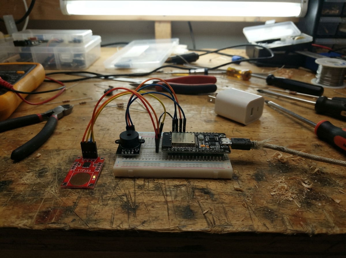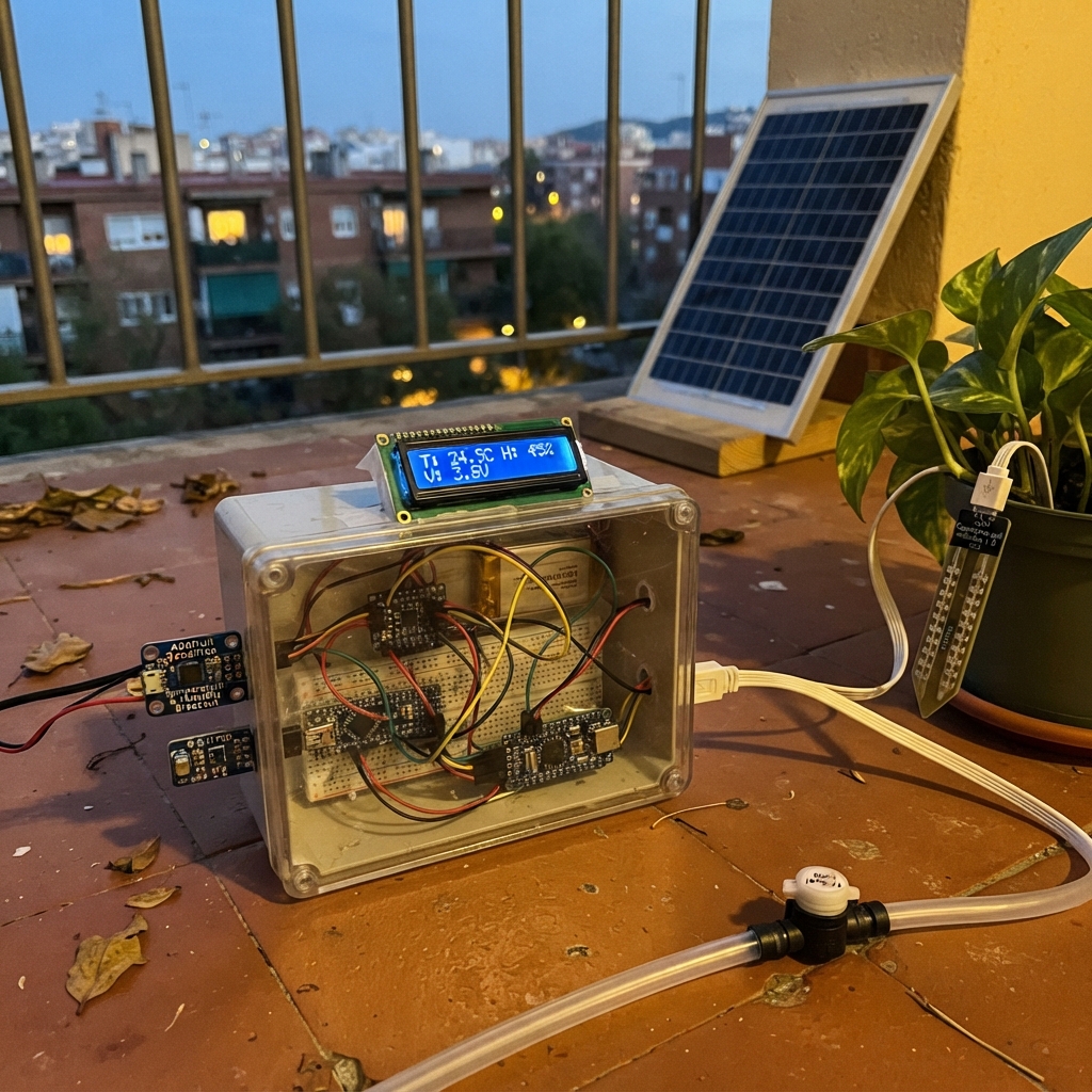
This solar-powered plant care system monitors soil moisture, temperature, humidity, and light levels to automatically water and ventilate plants while running entirely off a rechargeable battery charged by a small solar panel. The ESP32 microcontroller reads data from multiple sensors, displays readings on an LCD screen, and controls a submersible pump, fan, and grow light through switched outputs based on configurable thresholds.
Builders will receive a complete wiring diagram, parts list with safe power assembly guidance, calibration procedures for the dual soil moisture probes, and Arduino firmware with a local web dashboard for monitoring and configuration. The guide covers power system assembly with the solar charger and battery protection, sensor integration through an I2C level shifter, flow rate measurement, and supervised testing to ensure reliable operation.
Wiring diagram
Gather all the parts
Assemble it in 8 steps
1. Buy the specified safe power parts
Choose the ESP32-S3-DevKitC-1 with an N16R8 module. This firmware uses internal RAM and a conservative flash layout, so it does not need PSRAM. Use a factory protected 3.7V 1S2P 4000mAh pack, the Adafruit 6106 charger, and three Adafruit 5648 switching modules instead of the TP4056 and relays.
- Do not parallel salvaged cells yourself. Never use a 7.4V two-cell series pack. Keep lithium batteries shaded, dry and away from hot enclosures.
2. Connect solar charging and battery
With everything unplugged, connect pack positive through the 2A inline fuse to charger BAT; pack negative to charger GND. Confirm connector polarity, not just wire colour. Panel positive goes to VIN and panel negative to GND. Leave charger battery chemistry and charge settings at their 4.2V Li-ion defaults; use a pack rated for at least 1A charging.
- This 1-2W panel is for a solar-assisted demonstration, not continuous self-powered operation. Use the charger's USB input for supplemental charging.
3. Wire the regulated power rail
Charger 5V output goes to the ESP32 board 5V pin and the 5V distribution rail; all ground wires share GND. Add the 1000uF capacitor across 5V and GND, stripe to GND. Verify 5V with a meter before attaching the board. Use soldered power connections or terminal blocks, not breadboard motor-current paths.
- Disconnect charger 5V from the ESP32 5V pin before plugging ESP32 USB into the computer. Never feed external 5V and USB power into the board together. For USB-only firmware testing, leave external power disconnected and the actuators unplugged.
4. Connect the air, light and soil sensors
SHT31 and BH1750: VCC to 3V3, GND to GND, SDA to GPIO8 (data), SCL to GPIO9 (clock). BH1750 ADDR goes to GND. Both soil probes use 3V3 and GND; probe 1 AOUT goes to GPIO1 and probe 2 AOUT to GPIO2. Buy v1.2 probes explicitly compatible with 3.3V.
- Keep probe electronics above the soil and dry. Put both probes in the same watering zone, away from direct water jets. Shield the air sensor from sun and splashes.
5. Connect the LCD through the voltage converter
Use a BSS138 board with its onboard pullups. LV to 3V3, HV to 5V, GND to GND. Low-side channel 1 to GPIO8, low-side channel 2 to GPIO9. High-side channel 1 to LCD SDA and channel 2 to LCD SCL. LCD VCC to 5V, GND to GND. The project calls these channels SDA_L/SDA_H and SCL_L/SCL_H. Use the common PCF8574 backpack set to address 0x27. Adjust its contrast screw; the backlight stays off to save power.
- Never connect a 5V LCD backpack's data wires directly to the ESP32.
6. Fit the flow sensor and voltage dividers
YF-S401 red to 5V, black to GND. Yellow goes through 10k to GPIO4; connect 15k between GPIO4 and GND. This reduces the 5V pulse to about 3V. Battery measurement: charger BAT through 100k to GPIO5, then another 100k from GPIO5 to GND.
- Install flow sensor after the pump, following its arrow. Keep the reservoir below the outlet to prevent siphoning. Use leak-tight tubing. Compare reported volume against a measured container; nominal calibration is 5880 pulses/litre and varies by sensor.
7. Wire the three switched loads
Each Adafruit 5648 driver: V+ to 5V and GND to common GND. Driver In pins: pump GPIO10, fan GPIO11, light GPIO12. Each In gets its own 100k resistor to GND so it stays off during reset. Each load positive goes to its driver's + output, and negative to its switched - output (Out), never directly to GND. These modules include flyback protection.
- Pump: <=250mA running and <=400mA startup. Fan: <=150mA running and <=400mA startup. Light: <=250mA, 5V strip with built-in series resistors only. Shorten the strip as needed; a full 30-50cm piece may exceed this limit. Total measured 5V peak must stay below the charger's 1A rating. Only one load runs at a time.
8. Calibrate and test under supervision
Keep the pump submerged and route its outlet into a measuring container before watering a plant. After deployment, join PlantSolar-Setup with password PlantDemo42 and open http://192.168.4.1. Optionally save home Wi-Fi details; the status shows its local IP. Calibrate each probe using dry soil and fully wet drained soil. Arm only after confirming the readings. Arming is never remembered after restart.
- Both probes below 35% trigger one shared watering zone after a 30-minute wait, maximum 5 seconds or 100mL per cycle. No pulses after 3 seconds latches a fault. Maximum pump time is 30 seconds per hour of uptime. Resetting restarts the 30-minute wait. Fan runs briefly above 30C or 85%RH; the light is a limited low-light demo, not a daily grow-light schedule.
- Battery below 3.5V disables loads, with recovery above 3.8V; voltage is approximate, not a charge percentage. This does not replace the pack protection circuit. Verify the divider reading with a meter.
- A small pump may not overcome the flow sensor restriction. If a water test produces a flow fault, do not bypass protection: choose a pump meeting the specified current limit and sufficient flow, or redesign the power supply. Do not leave this demonstration unattended. The local dashboard has no Internet security; do not port-forward it.
Review all connections
1. Connections between "sht" and "ESP32"
2. Connections between "lux" and "ESP32"
3. Connections between "soil1" and "ESP32"
4. Connections between "soil2" and "ESP32"
5. Connections between "lcd" and "ESP32"
6. Connections between "shift" and "ESP32"
7. Connections between "flow" and "ESP32"
8. Connections between "rtop" and "ESP32"
9. Connections between "rbottom" and "ESP32"
10. Connections between "battery" and "ESP32"
11. Connections between "fuse" and "ESP32"
12. Connections between "charger" and "ESP32"
13. Connections between "panel" and "ESP32"
14. Connections between "batrtop" and "ESP32"
15. Connections between "batrbottom" and "ESP32"
16. Connections between "bulk" and "ESP32"
17. Connections between "pumpdrv" and "ESP32"
18. Connections between "pump" and "ESP32"
19. Connections between "pumppd" and "ESP32"
20. Connections between "fandrv" and "ESP32"
21. Connections between "fan" and "ESP32"
22. Connections between "fanpd" and "ESP32"
23. Connections between "lightdrv" and "ESP32"
24. Connections between "light" and "ESP32"
25. Connections between "lightpd" and "ESP32"
Deploy the firmware
#include <Arduino.h>
#include <Wire.h>
#include <WiFi.h>
#include <WebServer.h>
#include <Preferences.h>
#include <Adafruit_SHT31.h>
#include <BH1750.h>
#include <LiquidCrystal_I2C.h>

constexpr int SOIL1=1, SOIL2=2, FLOW=4, BATTERY=5, PUMP=10, FAN=11, LIGHT=12;
WebServer web(80);
Preferences prefs;
Adafruit_SHT31 sht;
BH1750 bh;
LiquidCrystal_I2C lcd(0x27,16,2);
volatile uint32_t pulses=0;
void IRAM_ATTR pulseISR(){pulses++;}
uint32_t pulseCount(){noInterrupts(); uint32_t n=pulses; interrupts();return n;}
bool shtOK=false,bhOK=false,lcdOK=false, armed=false, fault=false, lowBattery=true;
bool pump=false,fan=false,light=false;
int raw[2]={0,0},dry[2]={0,0},wet[2]={0,0},moist[2]={0,0};
float temp=NAN,rh=NAN,lux=NAN,bat=0,flowRate=0;
float pulsesPerLiter=5880;
uint32_t sampled=0,cycleStart=0,cyclePulses=0,lastFlow=0,lastPulse=0;
uint32_t cooldown=0,windowStart=0,usedPumpMs=0,fanStart=0,lightStart=0;
String ssid,pass, previous[2];
const char PAGE[] PROGMEM=R"HTML(<!doctype html><html><meta name="viewport" content="width=device-width"><title>Plant Solar Demo</title>
<h2>Plant Solar Demo</h2><p>Local dashboard. No cloud required.</p><pre id="v">Loading...</pre>
<form action="/wifi" method="post">Home Wi-Fi name <input name="ssid" maxlength="32"><br>Password <input name="pass" type="password" maxlength="63"><button>Save and connect</button></form>
<p>Calibrate each probe in dry soil, then fully wet, drained soil. Keep its electronics dry. Percent is a relative index, not scientific water content.</p>
<form action="/cal" method="post"><select name="probe"><option value="0">Probe 1</option><option value="1">Probe 2</option></select><button name="point" value="dry">Save dry</button><button name="point" value="wet">Save wet</button></form>
<form action="/arm" method="post"><button name="on" value="1">Arm automatic care</button><button name="on" value="0">STOP / disarm</button></form>
<form action="/clear" method="post"><button>Clear flow fault after checking water</button></form>
<p>One watering zone: both probes must be dry. Max 5 seconds/cycle, 30 minutes between cycles, 30 seconds per rolling hour of uptime. Reboot starts a 30-minute wait. Fan and light are demonstration duty cycles, not full climate control.</p>
<script>setInterval(()=>fetch('/status').then(r=>r.json()).then(v=>document.getElementById('v').textContent=JSON.stringify(v,null,2)),2000);</script></html>)HTML";
int avg(int pin){uint32_t s=0;for(int i=0;i<16;i++)s+=analogRead(pin);return s/16;}
bool calibrated(){return dry[0]-wet[0]>150 && dry[1]-wet[1]>150;}
bool validSoil(){return raw[0]>100 && raw[0]<4000 && raw[1]>100 && raw[1]<4000;}
void stopPump(){if(pump){usedPumpMs+=millis()-cycleStart;cooldown=millis();}pump=false;digitalWrite(PUMP,LOW);}
void allOff(){stopPump();fan=light=false;digitalWrite(FAN,LOW);digitalWrite(LIGHT,LOW);}
void reply(){web.sendHeader("Location","/");web.send(303,"text/plain","");}
String number(float f,int places=1){return isfinite(f)?String(f,places):String("null");}
void status(){
 String s="{\"temperature_C\":"+number(temp)+",\"humidity_pct\":"+number(rh)+",\"lux\":"+number(lux)+",\"battery_V\":"+number(bat,2);
 s+=",\"soil1_raw\":"+String(raw[0])+",\"soil2_raw\":"+String(raw[1]);
 s+=",\"soil1_pct\":"+(calibrated()?String(moist[0]):String("null"))+",\"soil2_pct\":"+(calibrated()?String(moist[1]):String("null"));
 s+=",\"flow_L_min\":"+number(flowRate,3)+",\"volume_L_since_boot\":"+String(pulseCount()/pulsesPerLiter,3);
 s+=",\"armed\":"+String(armed?"true":"false")+",\"flow_fault\":"+String(fault?"true":"false")+",\"low_battery\":"+String(lowBattery?"true":"false");
 s+=",\"pump\":"+String(pump?"true":"false")+",\"fan\":"+String(fan?"true":"false")+",\"light\":"+String(light?"true":"false")+",\"station_ip\":\""+WiFi.localIP().toString()+"\"}";
 web.send(200,"application/json",s);
}
void showLine(int row,String s){while(s.length()<16)s+=' ';s=s.substring(0,16);if(s!=previous[row]){lcd.setCursor(0,row);lcd.print(s);previous[row]=s;}}
void setup(){
 for(int p:{PUMP,FAN,LIGHT}){digitalWrite(p,LOW);pinMode(p,OUTPUT);}Serial.begin(115200);
 pinMode(FLOW,INPUT);attachInterrupt(digitalPinToInterrupt(FLOW),pulseISR,RISING);
 analogReadResolution(12);analogSetAttenuation(ADC_11db);Wire.begin(8,9);Wire.setClock(100000);Wire.setTimeOut(50);
 shtOK=sht.begin(0x44);bhOK=bh.begin(BH1750::CONTINUOUS_HIGH_RES_MODE);
 Wire.beginTransmission(0x27);lcdOK=Wire.endTransmission()==0;
 if(lcdOK){lcd.init();lcd.noBacklight();}
 prefs.begin("plant",false);for(int i=0;i<2;i++){dry[i]=prefs.getInt(("dry"+String(i)).c_str(),0);wet[i]=prefs.getInt(("wet"+String(i)).c_str(),0);}
 ssid=prefs.getString("ssid","");pass=prefs.getString("pass","");
 WiFi.mode(WIFI_AP_STA);WiFi.softAP("PlantSolar-Setup","PlantDemo42");if(ssid.length())WiFi.begin(ssid.c_str(),pass.c_str());
 web.on("/",HTTP_GET,[]{web.send_P(200,"text/html",PAGE);});web.on("/status",HTTP_GET,status);
 web.on("/wifi",HTTP_POST,[]{ssid=web.arg("ssid");pass=web.arg("pass");prefs.putString("ssid",ssid);prefs.putString("pass",pass);WiFi.begin(ssid.c_str(),pass.c_str());reply();});
 web.on("/cal",HTTP_POST,[]{int i=web.arg("probe").toInt();if(i>=0&&i<2&&!pump){int n=avg(i?SOIL2:SOIL1);String key=web.arg("point");if(key=="dry"||key=="wet"){if(key=="dry")dry[i]=n;else wet[i]=n;prefs.putInt((key+String(i)).c_str(),n);armed=false;allOff();}}reply();});
 web.on("/arm",HTTP_POST,[]{armed=web.arg("on")=="1"&&calibrated()&&validSoil()&&!lowBattery&&!fault;if(!armed)allOff();reply();});
 web.on("/clear",HTTP_POST,[]{allOff();armed=false;fault=false;cooldown=millis();reply();});
 web.begin();cooldown=windowStart=millis();Serial.println("Connect PlantSolar-Setup / PlantDemo42 then open http://192.168.4.1");
}
void loop(){
 web.handleClient();uint32_t now=millis();
 if(now-sampled>=2000 || sampled==0){sampled=now;
  raw[0]=avg(SOIL1);raw[1]=avg(SOIL2);
  for(int i=0;i<2;i++)if(dry[i]-wet[i]>150)moist[i]=constrain((dry[i]-raw[i])*100/(dry[i]-wet[i]),0,100);
  uint32_t mv=0;for(int i=0;i<16;i++)mv+=analogReadMilliVolts(BATTERY);bat=mv/16.0f*2/1000;
  if(bat<3.5 || bat>4.3)lowBattery=true;else if(bat>3.8)lowBattery=false;
  temp=shtOK?sht.readTemperature():NAN;rh=shtOK?sht.readHumidity():NAN;
  lux=bhOK?bh.readLightLevel():NAN;if(lux<0)lux=NAN;
  uint32_t n=pulseCount();if(lastFlow)flowRate=(n-lastPulse)*60000.0f/(now-lastFlow)/pulsesPerLiter;lastFlow=now;lastPulse=n;
  if(lcdOK){if((now/5000)%2){showLine(0,"Soil "+String(moist[0])+"/"+String(moist[1])+"%");showLine(1,fault?"FLOW FAULT":(armed?"ARMED ":"SAFE ")+String(bat,2)+"V");}else{showLine(0,String(temp,1)+"C "+String(rh,0)+"%RH");showLine(1,"Lux "+String(lux,0));}}
 }
 if(!armed||lowBattery||!validSoil()||!calibrated()){allOff();return;}
 if(now-windowStart>=3600000UL){windowStart=now;usedPumpMs=0;}
 if(pump){
  if(now-cycleStart>=3000 && pulseCount()==cyclePulses){fault=true;armed=false;allOff();}
  else if(now-cycleStart>=5000 || pulseCount()-cyclePulses>=uint32_t(pulsesPerLiter*.1f) || usedPumpMs+(now-cycleStart)>=30000)stopPump();
  return;
 }
 if(!fault && moist[0]<35 && moist[1]<35 && now-cooldown>=1800000UL && usedPumpMs<30000){
  fan=light=false;digitalWrite(FAN,LOW);digitalWrite(LIGHT,LOW);pump=true;cycleStart=now;cyclePulses=pulseCount();digitalWrite(PUMP,HIGH);return;
 }
 // Time-sliced demonstration limits: fan <=60s/5min, light <=60s/10min.
 bool wantFan=isfinite(temp)&&isfinite(rh)&&(temp>=30||rh>=85)&&(now%300000UL<60000);
 bool wantLight=!wantFan&&isfinite(lux)&&lux<1000&&(now%600000UL>=60000&&now%600000UL<120000);
 fan=wantFan;light=wantLight;digitalWrite(FAN,fan);digitalWrite(LIGHT,light);
 delay(2);
}
Remix this project
Make it yours in one click
Open a full copy of this project in your own Schematik workspace, diagram, code, parts, and assembly steps included. Swap the sensor, add features, or redesign the whole thing with AI. The author's original stays untouched.