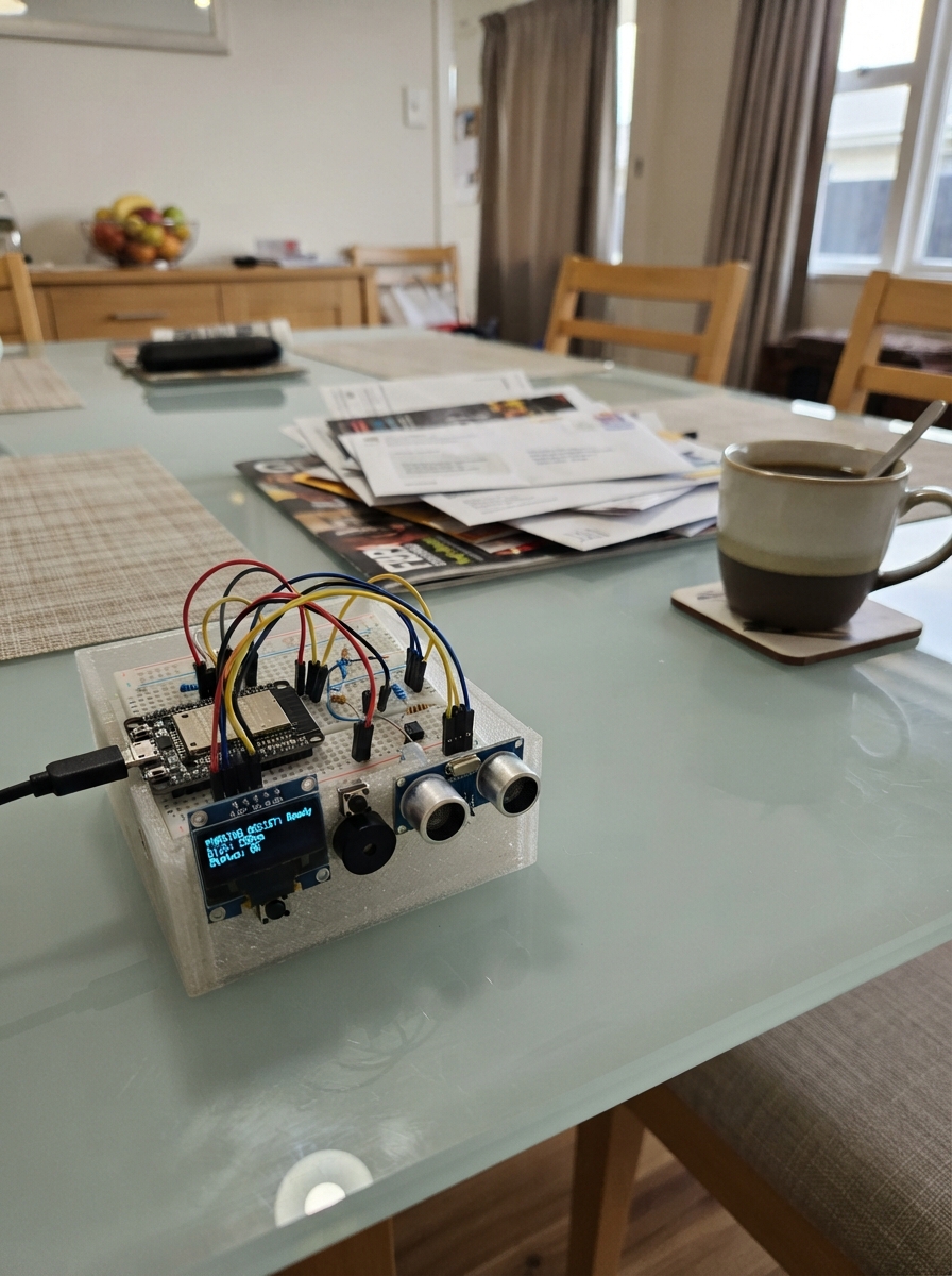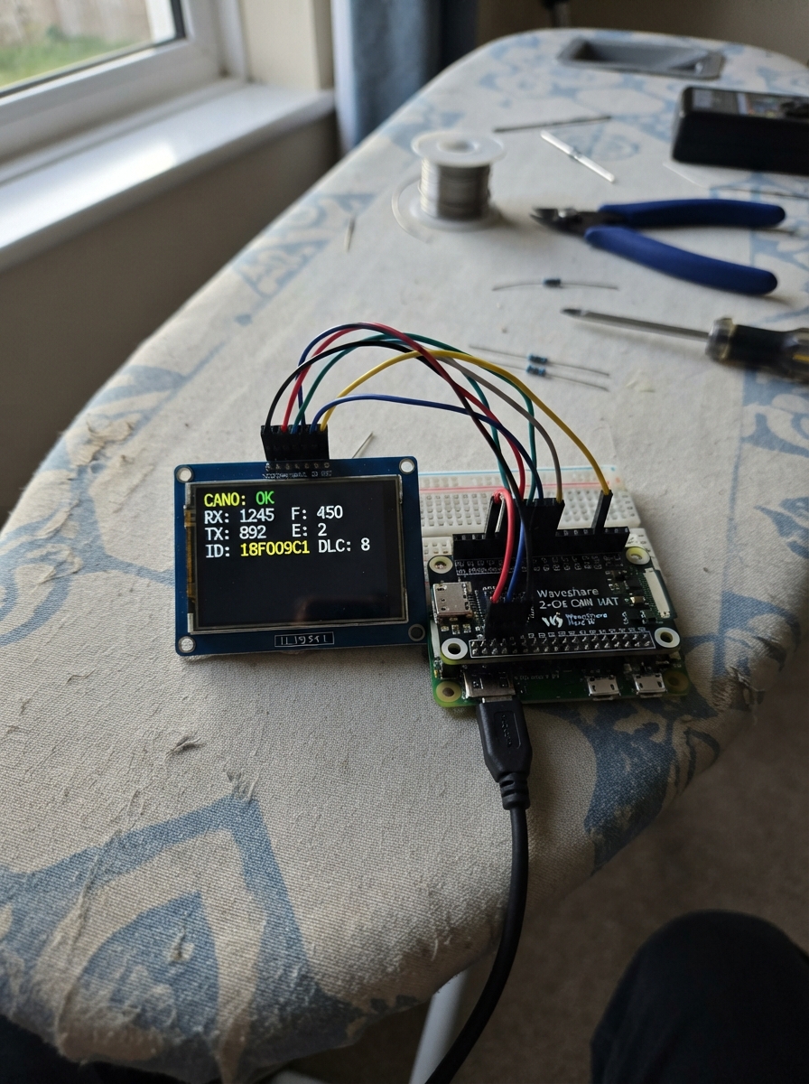
This project builds a real-time CAN bus monitor using an ESP32, a dual-channel CAN HAT, and a 2.4-inch ILI9341 display. The monitor listens to two independent CAN bus networks simultaneously and shows frame IDs, data length codes, payload bytes, and link health status on the LCD in listen-only mode.
The guide includes a complete wiring diagram showing SPI connections between the ESP32 and display, CAN HAT voltage configuration, and safe test network setup. Builders will receive the full Arduino firmware, a parts list with pinout details, and step-by-step assembly instructions to get both CAN channels receiving and displaying frames within minutes.
Wiring diagram
Gather all the parts
Assemble it in 4 steps
1. Set the CAN HAT voltage first
With USB unplugged, set the HAT VIO jumper to 3.3V. Its power input still needs 5V. Connect HAT 5V to ESP32 5V and GND to GND.
- A 5V VIO setting can damage the ESP32. Never connect vehicle battery voltage to the ESP32 or HAT.
2. Connect the shared communication wires
Connect HAT MOSI and LCD DIN to GPIO23 (data out). Connect HAT SCK and LCD CLK to GPIO18 (clock). Connect HAT MISO to GPIO19 (data in). HAT CS_0 goes to GPIO25 and CS_1 to GPIO26 (channel selection). Interrupt pins are unused because firmware polls both CAN0 and CAN1.
3. Connect the screen controls
LCD VCC goes to 3V3 and GND to GND. CS goes to GPIO21 (screen selection), DC to GPIO22 (commands or pixels), RST to GPIO17 (reset), and BL to GPIO16 (backlight). Treat the label RTS as RST/reset, not a serial flow-control pin. Use the 8-pin ILI9341 module with onboard backlight resistors and driver.
4. Connect a safe CAN test network
Connect CAN0_H and CAN0_L to the matching high and low wires of the first test bus. Connect CAN1_H and CAN1_L to a second test bus if wanted; either channel can be used alone. Firmware listens on both channels at 1 Mbit/s (1000 kbit/s); this must match each bus speed. Enable each onboard 120-ohm termination jumper only when that channel is at an end of its bus. Exactly two terminations belong on each bus. Keep wires short and twisted together.
- This firmware is permanently listen-only and never transmits or acknowledges frames. An active sender and another acknowledging node are needed for a normal test bus. This supports classic CAN only
- not CAN FD.
Review all connections
1. Connections between "lcd" and "ESP32"
2. Connections between "hat" and "ESP32"
Deploy the firmware
#include <Arduino.h>
#include <SPI.h>
#include <Adafruit_GFX.h>
#include <Adafruit_ILI9341.h>
#include <mcp_can.h>
Adafruit_ILI9341 lcd(&SPI,22,21,17);
MCP_CAN c0(25),c1(26);
MCP_CAN* channels[]={&c0,&c1};
bool healthy[2]={false,false},dirty=true;
uint32_t received[2]={0,0},lastDraw=0;
String frameId[2]={"--","--"},payload[2]={"Waiting for frames","Waiting for frames"};
uint8_t frameLength[2]={0,0};
bool extended[2]={false,false},remote[2]={false,false};
void text(int x,int y,const String&s,uint16_t color,int size=1){lcd.setCursor(x,y);lcd.setTextColor(color);lcd.setTextSize(size);lcd.print(s);}
void draw(){
 lcd.fillRect(0,62,320,178,ILI9341_BLACK);
 for(int i=0;i<2;i++){
  int y=64+i*78;
  text(8,y,String("CAN")+i+"  1 Mbit/s",ILI9341_CYAN,2);
  text(8,y+19,healthy[i]?String("LISTEN ONLY  RX: ")+received[i]:"CONTROLLER ERROR",healthy[i]?ILI9341_GREEN:ILI9341_RED);
  text(8,y+33,String("ID: ")+frameId[i]+" DLC:"+frameLength[i]+(remote[i]?" RTR":extended[i]?" EXT":" STD"),ILI9341_YELLOW);
  text(8,y+48,"RX DATA:",ILI9341_CYAN);
  text(8,y+61,payload[i],ILI9341_WHITE);
 }
 text(8,226,"Classic CAN | No transmit or ACK",ILI9341_WHITE);
 dirty=false;
}
void setup(){Serial.begin(115200);for(int p:{21,25,26}){pinMode(p,OUTPUT);digitalWrite(p,HIGH);}pinMode(16,OUTPUT);digitalWrite(16,LOW);SPI.begin(18,19,23);lcd.begin(20000000);lcd.setRotation(1);lcd.fillScreen(ILI9341_BLACK);digitalWrite(16,HIGH);text(82,72,"LOADING",ILI9341_WHITE,2);lcd.drawRect(19,119,282,6,ILI9341_WHITE);text(64,140,"Renesans service",ILI9341_WHITE,2);text(40,166,"MASTER CAN BUS TOOLS",ILI9341_CYAN,2);uint32_t start=millis();int previous=-1;while(millis()-start<8000){int w=(millis()-start)*280/8000;if(w!=previous){lcd.fillRect(20+max(previous,0),120,w-max(previous,0),4,ILI9341_GREEN);previous=w;}delay(5);}lcd.fillRect(20,120,280,4,ILI9341_GREEN);lcd.fillScreen(ILI9341_BLACK);text(10,6,"RENESANS ELECTRONICS",ILI9341_WHITE,2);text(10,28,"TURKU +44 240 9665",ILI9341_YELLOW,2);lcd.drawFastHLine(0,54,320,ILI9341_CYAN);for(int i=0;i<2;i++){healthy[i]=channels[i]->begin(MCP_ANY,CAN_1000KBPS,MCP_16MHZ)==CAN_OK;if(healthy[i])healthy[i]=channels[i]->setMode(MCP_LISTENONLY)==CAN_OK;} draw();}
void loop(){
 for(int k=0;k<32;k++){
  bool any=false;
  for(int i=0;i<2;i++){
   if(!healthy[i] || channels[i]->checkReceive()!=CAN_MSGAVAIL)continue;
   any=true;
   unsigned long id; uint8_t n=0,data[8]={};
   if(channels[i]->readMsgBuf(&id,&n,data)==CAN_OK){
    n=min(n,uint8_t(8));received[i]++;
    extended[i]=(id&0x80000000UL)!=0;remote[i]=(id&0x40000000UL)!=0;
    char value[12];snprintf(value,sizeof(value),extended[i]?"%08lX":"%03lX",id&0x1fffffffUL);frameId[i]=value;
    frameLength[i]=n;payload[i]=remote[i]?"Remote request":"";
    if(!remote[i])for(int j=0;j<n;j++){char h[4];snprintf(h,sizeof(h),"%02X ",data[j]);payload[i]+=h;}
    dirty=true;
   }
  }
  if(!any)break;
 }
 if(dirty && millis()-lastDraw>=250){lastDraw=millis();draw();}
}
Remix this project
Make it yours in one click
Open a full copy of this project in your own Schematik workspace, diagram, code, parts, and assembly steps included. Swap the sensor, add features, or redesign the whole thing with AI. The author's original stays untouched.