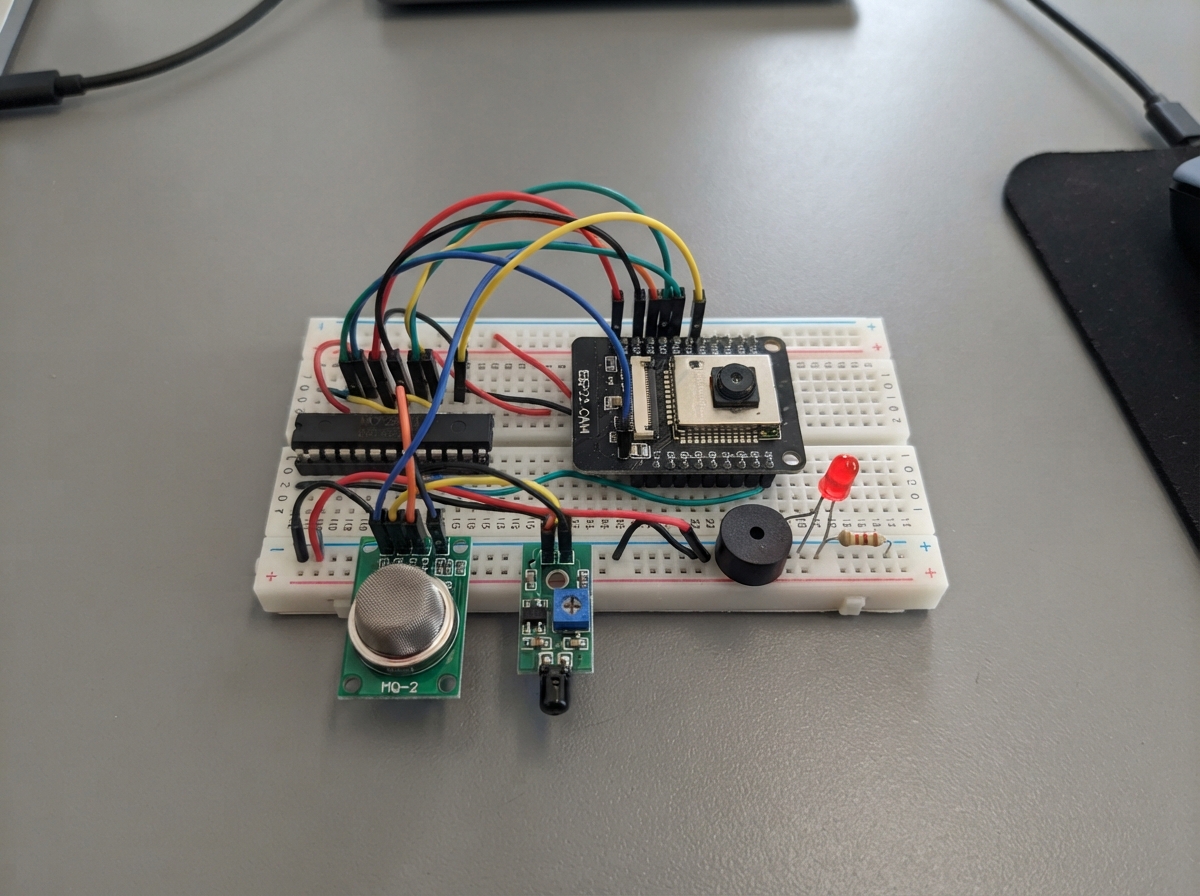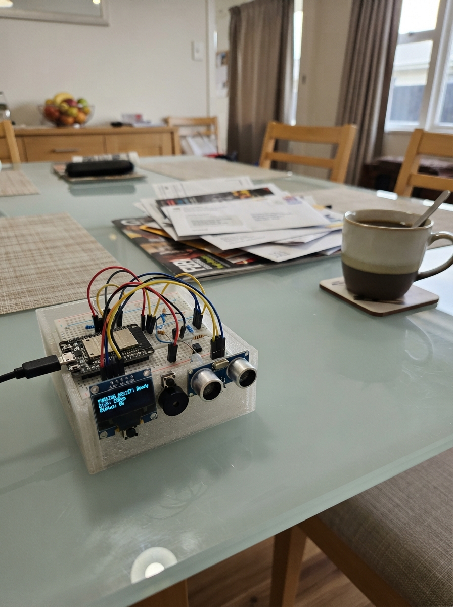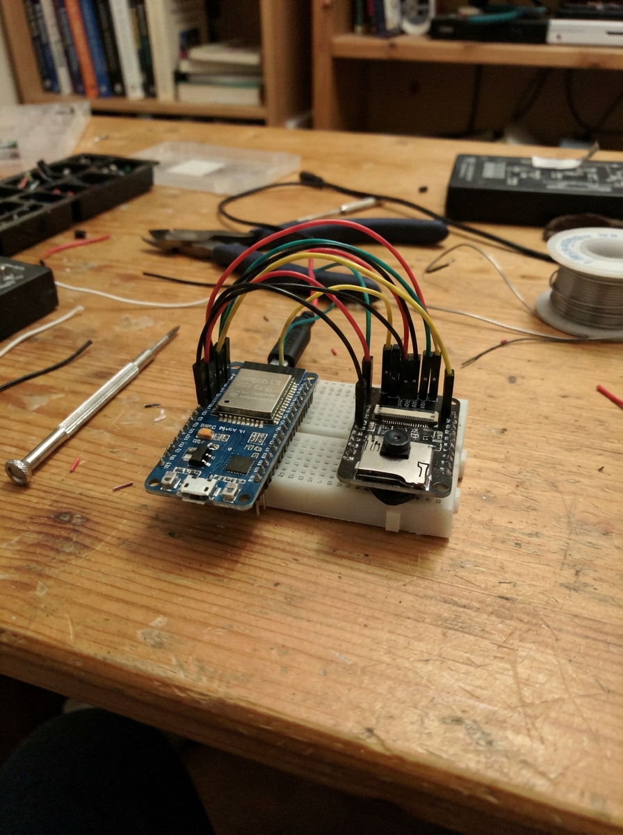
This guide shows how to program an ESP32-CAM module using an ESP32 DevKit V1 as a USB-UART bridge. The DevKit's onboard USB-to-serial chip connects to the ESP32-CAM's serial pins, allowing firmware uploads and serial communication without needing a dedicated programmer. The guide includes a wiring diagram, parts list, step-by-step assembly instructions, and test firmware that echoes serial input and reports uptime.
The ESP32-CAM lacks a built-in USB interface, making direct programming difficult. By repurposing a DevKit as a programmer—keeping its processor in reset while using only its USB and serial hardware—makers can flash and debug ESP32-CAM projects with common tools. This approach requires manual download-mode selection but eliminates the need for specialized hardware.
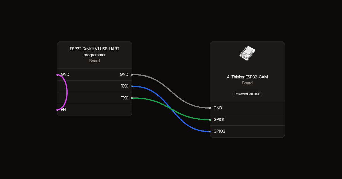
Wiring diagram
Gather all the parts
Assemble it in 5 steps
1. Disable the DevKit processor
Unplug USB. Connect the DevKit EN pin to its GND pin. Leave this wire installed during programming and debugging. Its USB-UART chip still operates.
- Do not run the DevKit processor while these UART wires are connected: two transmitters could fight each other.
2. Connect the serial wires
Connect DevKit RX0 (GPIO3) to ESP32-CAM U0R (GPIO3), DevKit TX0 (GPIO1) to ESP32-CAM U0T (GPIO1), and GND to GND. These apparently same-name connections are intentional because the DevKit processor is disabled.
- Use short jumper wires. Do not use RX2 or TX2.
3. Connect USB power
Connect the DevKit USB-derived 5V pin (often labeled VIN) to the ESP32-CAM 5V input. Verify your DevKit exposes USB 5 V on that pin before using it. Leave both 3V3 pins unconnected.
- UART signals must be 3.3 V, never 5 V. USB power through the DevKit may be insufficient for camera operation; unstable power can cause resets and failed uploads. Do not connect another 5 V supply to this shared power wire.
4. Select download mode manually
Temporarily connect ESP32-CAM IO0 to its GND. Press and release the ESP32-CAM onboard RST button to sample IO0 low. Keep the DevKit EN-to-GND wire in place.
- The temporary IO0 wire is a mode selector, not a permanent application connection. Remove any microSD card for the initial test.
5. Return to normal operation
Remove the ESP32-CAM IO0-to-GND jumper and press its RST button after programming. Keep power, UART, ground, and the DevKit EN-to-GND connection installed for serial debugging.
- Remove the IO0 jumper before running camera firmware: IO0 also carries the camera clock.
Review all connections
1. Connections between "programmer" and "ESP32"
Deploy the firmware
#include <Arduino.h>
// This firmware runs on the ESP32-CAM, NOT the programmer DevKit.
// The DevKit ESP32 stays in hardware reset; its USB-UART needs no sketch.
static uint32_t lastReport = 0;
void setup() {
  Serial.begin(115200);
  delay(300);
  Serial.println("ESP32-CAM serial test ready. Type characters to echo them.");
}
void loop() {
  while (Serial.available() > 0) {
    const int c = Serial.read();
    if (c >= 0) Serial.write(static_cast<uint8_t>(c));
  }
  const uint32_t now = millis();
  if (now - lastReport >= 5000) {
    lastReport = now;
    Serial.printf("\r\nESP32-CAM uptime: %lu seconds\r\n",
                  static_cast<unsigned long>(now / 1000));
  }
  delay(1);
}
Remix this project
Make it yours in one click
Open a full copy of this project in your own Schematik workspace, diagram, code, parts, and assembly steps included. Swap the sensor, add features, or redesign the whole thing with AI. The author's original stays untouched.