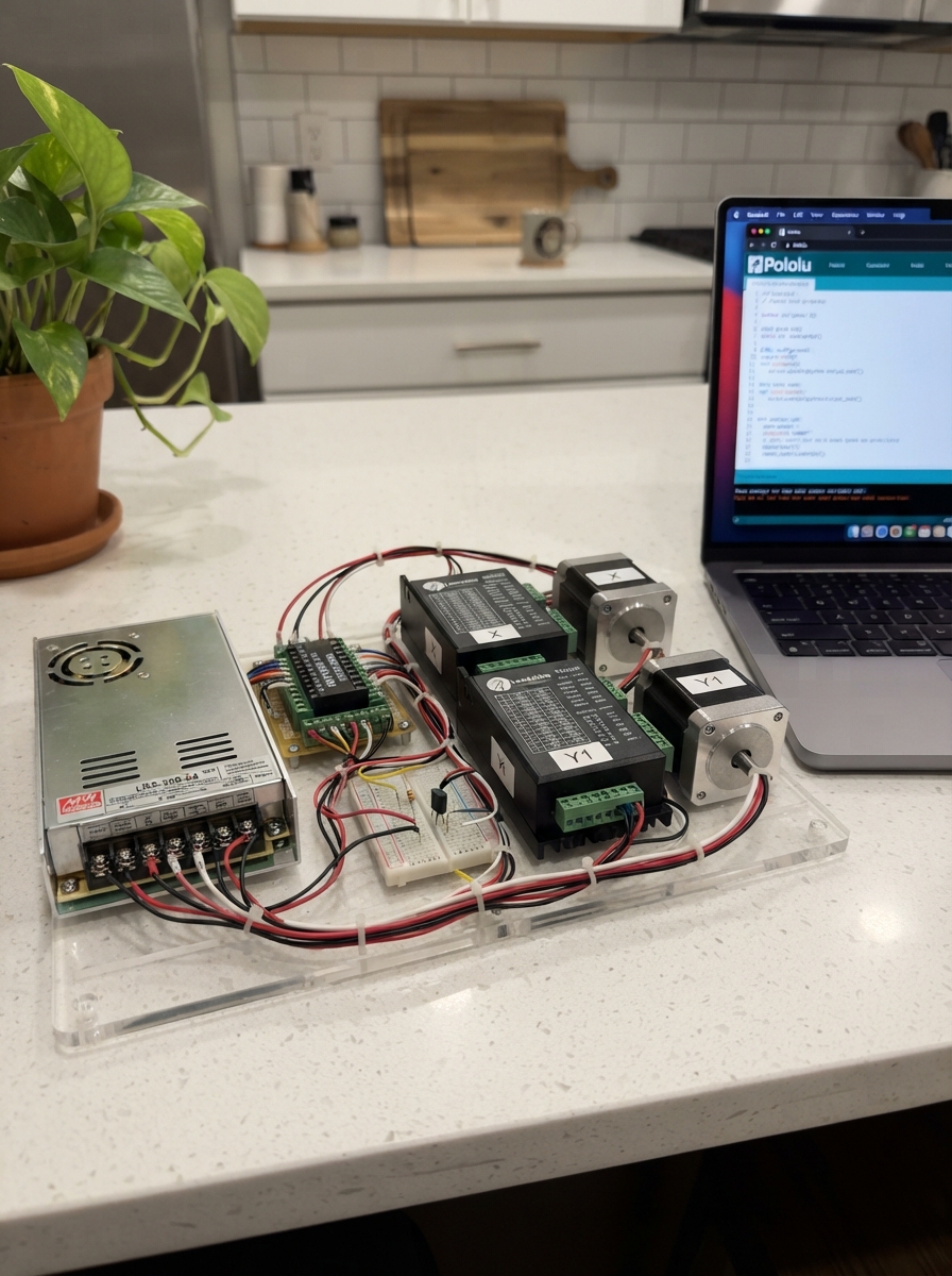
This four-axis synchronized CNC engraving machine uses an ESP32 microcontroller to coordinate independent stepper motors on X, Y (dual motors), and Z axes. The build combines Leadshine DM556 stepper drivers with 42CM06D motors, a Mean Well 350W power supply, and signal conditioning via 2N3904 transistors to create a compact routing and engraving platform.
This guide provides a complete wiring diagram, parts list, and step-by-step assembly instructions for integrating the motor drivers, power distribution, and control electronics. The included firmware enables basic jog commands via USB serial interface (no G-code required), allowing makers to test axis movement and calibrate the machine before adding advanced motion control or CAM software.
Wiring diagram
Gather all the parts
Assemble it in 5 steps
1. 先脱开机械负载
断电,四台电机先不连接丝杆或皮带。固定电机本体,轴上不要装刀具。该项目仅验线,不可加工。
- 无限位、无归零、无硬件急停;禁止连接主轴或带负载试车。
2. 安装转接板
MRD076A只是接线转接板。核对开发板与插座方向和全部电源脚,断电用万用表确认标为4至11的端子分别通向对应GPIO,而不是按排针位置数。无法确认就不要插板上电。ESP32只用USB供电。
- 24V接入MRD076A会烧毁开发板。不要同时向5V端子接第二路电源。
3. 制作八路信号接口
每路使用一只2N3904、一只1kΩ基极串联电阻和一只10kΩ基极到地电阻。GPIO经1kΩ到B;E到ESP32地;C到对应PUL-或DIR-;PUL+和DIR+到USB的5V。使用焊接板固定,按购买厂商资料识别B/C/E,不猜腿序。
- X用GPIO4/5,Y1用6/7,Y2用8/9,Z用10/11,前者为脉冲、后者为方向。接口不是隔离板;DM556内部提供光耦输入。
4. 接电机与驱动器
断电测出每台电机的两对线圈,分别接A+/A-和B+/B-。每台电机单独一个DM556。ENA两端均不接。按本机说明设置5V控制输入、单脉冲STEP/DIR模式;初测选择最低电流档,细分建议四台均为1600脉冲/圈(若本机支持)。
- 不得设5.6A;正式电流需区分峰值与有效值并匹配2.5A/相电机。禁止带电插拔电机。不同DM556版本拨码不同,不照抄开关位置。
5. 完成受保护的电源接线
由电工完成L/N/FG接线、保护地与金属箱机架连接、交流保护、端子防触碰和导线固定。四个驱动器并联接24V,按实际线径完成支路保护后再上电;24V不经过MRD076A。此处6A是暂估直流总负载,不是保险选型值。
- 市电有致命触电风险;未完成保护不得上电。先接通USB控制电源,再接24V。停止脉冲不切断驱动电流;紧急情况使用安全可接近的电机电源断电装置。
Review all connections
1. Connections between "adapter" and "ESP32"
2. Connections between "psu" and "ESP32"
3. Connections between "drv_x" and "ESP32"
4. Connections between "motor_x" and "ESP32"
5. Connections between "rb_x_step" and "ESP32"
6. Connections between "pd_x_step" and "ESP32"
7. Connections between "q_x_step" and "ESP32"
8. Connections between "rb_x_dir" and "ESP32"
9. Connections between "pd_x_dir" and "ESP32"
10. Connections between "q_x_dir" and "ESP32"
11. Connections between "drv_y1" and "ESP32"
12. Connections between "motor_y1" and "ESP32"
13. Connections between "rb_y1_step" and "ESP32"
14. Connections between "pd_y1_step" and "ESP32"
15. Connections between "q_y1_step" and "ESP32"
16. Connections between "rb_y1_dir" and "ESP32"
17. Connections between "pd_y1_dir" and "ESP32"
18. Connections between "q_y1_dir" and "ESP32"
19. Connections between "drv_y2" and "ESP32"
20. Connections between "motor_y2" and "ESP32"
21. Connections between "rb_y2_step" and "ESP32"
22. Connections between "pd_y2_step" and "ESP32"
23. Connections between "q_y2_step" and "ESP32"
24. Connections between "rb_y2_dir" and "ESP32"
25. Connections between "pd_y2_dir" and "ESP32"
26. Connections between "q_y2_dir" and "ESP32"
27. Connections between "drv_z" and "ESP32"
28. Connections between "motor_z" and "ESP32"
29. Connections between "rb_z_step" and "ESP32"
30. Connections between "pd_z_step" and "ESP32"
31. Connections between "q_z_step" and "ESP32"
32. Connections between "rb_z_dir" and "ESP32"
33. Connections between "pd_z_dir" and "ESP32"
34. Connections between "q_z_dir" and "ESP32"
Deploy the firmware
#include <Arduino.h>
const uint8_t stepPins[]={4,6,8,10};
const uint8_t dirPins[]={5,7,9,11};
bool armed=false, moving=false, invertY2=false, pulseHigh=false;
uint8_t mask=0;
uint16_t remaining=0;
uint32_t nextEdge=0, lastCommand=0;
void stop(){for(auto p:stepPins) digitalWrite(p,LOW);moving=false;pulseHigh=false;remaining=0;}
void help(){Serial.println("ARM: allow one bounded jog; X+/X-/Y+/Y-/Z+/Z-: 100 pulses at 100Hz; STOP or !: stop pulses; DISARM; Y2INV: toggle Y2 direction (uncoupled motors only); HELP. No G-code, no homing, no limits. USB 115200. Each jog requires ARM.");}
void command(String s){s.trim();s.toUpperCase();lastCommand=millis();
 if(s=="STOP"||s=="DISARM"){stop();armed=false;Serial.println("Stopped pulses; drivers still hold torque.");return;}
 if(moving){Serial.println("Busy; STOP to abort.");return;}
 if(s=="HELP"){help();return;}
 if(s=="ARM"){armed=true;Serial.println("Armed for ONE jog, 10 second expiry. Uncouple motors first.");return;}
 if(s=="Y2INV"){invertY2=!invertY2;armed=false;Serial.printf("Y2 invert=%d\n",invertY2);return;}
 if(s.length()!=2||(s[1]!='+'&&s[1]!='-')){Serial.println("Unknown command.");return;}
 mask=s[0]=='X'?1:s[0]=='Y'?6:s[0]=='Z'?8:0;
 if(!mask||!armed){Serial.println("Use ARM first, then X+, X-, Y+, Y-, Z+, Z-.");return;}
 armed=false;
 for(int i=0;i<4;i++) if(mask&(1<<i))digitalWrite(dirPins[i],(s[1]=='+')^(i==2&&invertY2));
 remaining=100; moving=true; pulseHigh=false;nextEdge=micros()+1000;
 Serial.println("100-pulse jog starting.");
}
void setup(){for(int i=0;i<4;i++){digitalWrite(stepPins[i],LOW);digitalWrite(dirPins[i],LOW);pinMode(stepPins[i],OUTPUT);pinMode(dirPins[i],OUTPUT);}Serial.begin(115200);help();}
void loop(){static String line;
 while(Serial.available()){char c=Serial.read();if(c=='!'){stop();armed=false;line="";Serial.println("Stopped pulses.");}else if(c=='\n'||c=='\r'){if(line.length()){command(line);line="";}}else if(line.length()<32)line+=c;else{line="";stop();armed=false;}}
 if(armed&&millis()-lastCommand>10000)armed=false;
 uint32_t now=micros();
 if(moving&&(int32_t)(now-nextEdge)>=0){
  if(!pulseHigh){for(int i=0;i<4;i++)if(mask&(1<<i))digitalWrite(stepPins[i],HIGH);pulseHigh=true;nextEdge=micros()+100;}
  else{for(int i=0;i<4;i++)if(mask&(1<<i))digitalWrite(stepPins[i],LOW);pulseHigh=false;if(--remaining==0){stop();Serial.println("Jog done; disarmed.");}else nextEdge=micros()+9900;}
 }
}
Remix this project
Make it yours in one click
Open a full copy of this project in your own Schematik workspace, diagram, code, parts, and assembly steps included. Swap the sensor, add features, or redesign the whole thing with AI. The author's original stays untouched.