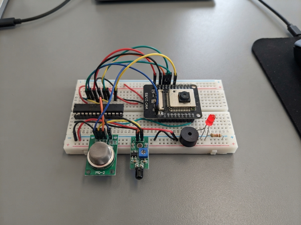
This project builds a dual-threat detection system that monitors for both flammable gases and open flames using an ESP32-CAM board. The MQ-2 gas sensor detects combustible vapors while the KY-026 flame sensor identifies infrared radiation from fire, with an MCP23017 I/O expander handling the sensor inputs and control outputs. The guide includes a complete wiring diagram, parts list, and Arduino firmware that triggers a piezo buzzer and LED indicators when hazards are detected, plus WiFi connectivity to send alerts via Telegram.
Following the assembly steps, readers will connect the camera module, configure the I/O expander over I2C, wire both sensors with proper debouncing logic, and set up the audio and visual alarm outputs. The firmware includes a 3-minute gas sensor warmup period, configurable active-high/low logic for different sensor modules, and a web server interface for monitoring status—all with detailed calibration guidance to ensure reliable detection in real environments.
Wiring diagram
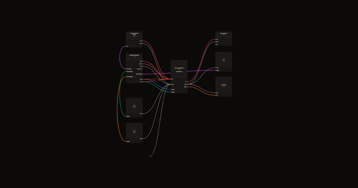
Gather all the parts
Assemble it in 6 steps
1. Prepare the camera board
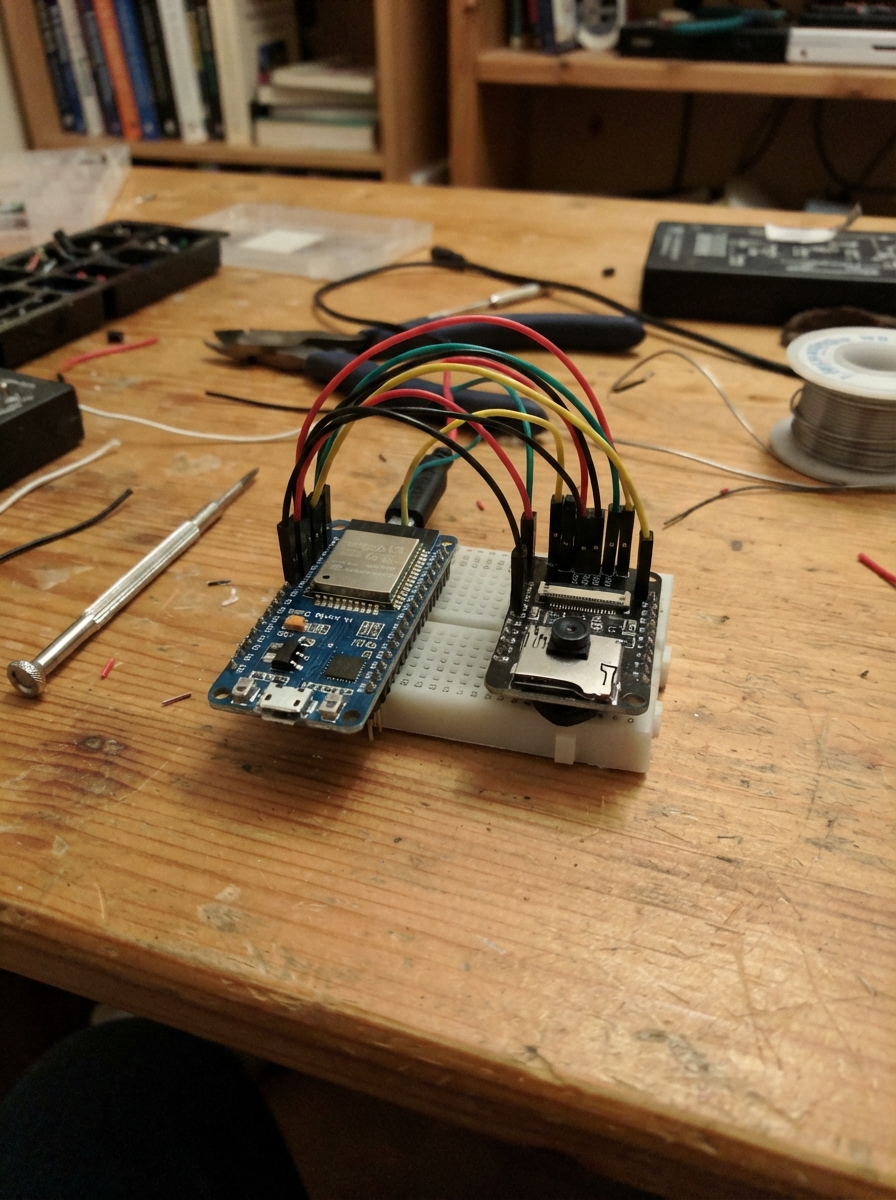
Use the AI Thinker ESP32-CAM with OV2640 camera installed. Leave the microSD slot empty. Use a regulated 5 V USB supply rated at least 1 A through an ESP32-CAM USB programmer base; all grounds must be connected together.
- This is a learning project
- not a certified fire or gas alarm. Keep certified alarms installed.
2. Connect the extra input and output chip
Use an MCP23017 at address 0x20. Tie its A0, A1 and A2 address pins to ground. VDD and RESET go to 3.3 V; VSS goes to ground. SDA goes to GPIO13 for data and SCL to GPIO14 for clock. Add the two 4.7 kΩ resistors from SDA and SCL to 3.3 V.
- The bank notation GPA0-GPA7[0] means the physical GPA0 pin. Check chip or breakout labels before wiring.
3. Connect the sensors
MQ-2 VCC goes to 5 V and GND to ground. DO goes through the 10 kΩ resistor to GPA0; connect the 15 kΩ resistor from that junction to ground. This reduces the 5 V signal to 3 V. KY-026 VCC goes to 3.3 V, GND to ground and DO to GPA1. Leave both AO pins unused.
- Never connect the MQ-2 output directly to a 3.3 V input. The sensor heater gets hot.
4. Connect the three indicators
GPA2 goes through its 1 kΩ resistor to the green LED long leg; GPA3 goes through its resistor to red; GPA4 goes through its resistor to orange. Every LED short leg goes to ground. Green means clear after warm-up, red means flame and orange means gas; both alarm lights can be on together.
5. Connect the alarm sounder
Connect the passive piezo SIG lead to GPIO3 and its other lead to ground. Disconnect the USB serial adapter TX wire from GPIO3 after flashing before running the sounder. The piezo shares the programming RX pin, not the camera pins.
- Do not use a magnetic or active buzzer in place of this passive piezo.
6. Adjust and check the sensors safely
Let the MQ-2 finish its initial conditioning as specified by its seller, often 24–48 hours. Every restart allows three minutes of warm-up; green stays off then. Set the sensor trimmers and check digital-output polarity on the bench. Gas and flame trigger levels are adjustable, not calibrated measurements. Flame detection needs a clear view and sunlight can cause false alarms.
- Do not release flammable gas or start a fire to test this project. Telegram needs working internet and is not guaranteed to arrive.
Review all connections
1. Connections between "io" and "ESP32"
2. Connections between "sda_pull" and "ESP32"
3. Connections between "scl_pull" and "ESP32"
4. Connections between "gas" and "ESP32"
5. Connections between "gas_top" and "ESP32"
6. Connections between "gas_bottom" and "ESP32"
7. Connections between "flame" and "ESP32"
8. Connections between "rg" and "ESP32"
9. Connections between "green" and "ESP32"
10. Connections between "rr" and "ESP32"
11. Connections between "red" and "ESP32"
12. Connections between "ro" and "ESP32"
13. Connections between "orange" and "ESP32"
14. Connections between "buzzer1" and "ESP32"
Deploy the firmware
#include <Arduino.h>
#include <Wire.h>
#include <WiFi.h>
#include <WiFiClientSecure.h>
#include <HTTPClient.h>
#include <WebServer.h>
#include "esp_camera.h"
// Fill these four values before Deploy. Never share your bot token.
const char* WIFI_NAME = "Inst";
const char* WIFI_PASSWORD = "deco9292";
const char* BOT_TOKEN = "YOUR_BOT_TOKEN";
const char* CHAT_ID = "YOUR_CHAT_ID";
// Most comparator modules trigger LOW. Change if your bench test shows otherwise.
const bool GAS_ACTIVE_LOW = true, FLAME_ACTIVE_LOW = true;
const uint32_t GAS_WARMUP_MS = 180000;
WebServer server(80);
volatile bool gasAlarm=false, fireAlarm=false, ioFault=false;
volatile uint8_t pending=0;
bool cameraOK=false;
void regWrite(uint8_t reg,uint8_t value){Wire.beginTransmission(0x20);Wire.write(reg);Wire.write(value);if(Wire.endTransmission()!=0)ioFault=true;}
int inputs(){Wire.beginTransmission(0x20);Wire.write(0x12);if(Wire.endTransmission(false)!=0)return -1;if(Wire.requestFrom(0x20,1)!=1)return -1;return Wire.read();}
void alarmTask(void*){
 uint8_t last=255; int gCount=0,fCount=0;
 for(;;){
 int in=inputs();ioFault=in<0;
 bool g=in>=0 && (((in&1)==0)==GAS_ACTIVE_LOW) && millis()>GAS_WARMUP_MS;
 bool f=in>=0 && (((in&2)==0)==FLAME_ACTIVE_LOW);
 gCount=g?min(gCount+1,5):max(gCount-1,0);fCount=f?min(fCount+1,5):max(fCount-1,0);
 bool ng=gCount==5?true:(gCount==0?false:gasAlarm);
 bool nf=fCount==5?true:(fCount==0?false:fireAlarm);
 if(ng&&!gasAlarm)pending|=1;if(nf&&!fireAlarm)pending|=2;
 gasAlarm=ng;fireAlarm=nf;
 bool ready=millis()>GAS_WARMUP_MS;
 uint8_t out=(!ng&&!nf&&ready&&!ioFault?4:0)|(nf?8:0)|(ng?16:0);
 if(out!=last){regWrite(0x14,out);last=out;}
 ledcWriteTone(3,(ng||nf||ioFault)?4000:0);
 vTaskDelay(pdMS_TO_TICKS(100));
 }
}
void telegramTask(void*){
 for(;;){
 if(pending && WiFi.status()==WL_CONNECTED && String(BOT_TOKEN)!="YOUR_BOT_TOKEN"){
 uint8_t item=(pending&1)?1:2;
 WiFiClientSecure tls;
 // Encryption enabled, but certificate validation disabled: see project warning.
 tls.setInsecure(); HTTPClient http;http.setTimeout(5000);
 String url="https://api.telegram.org/bot"+String(BOT_TOKEN)+"/sendMessage";
 if(http.begin(tls,url)){http.addHeader("Content-Type","application/x-www-form-urlencoded");
 String text=item==1?"Gas%20leak%20detected!":"Fire%20detected!";
 int code=http.POST("chat_id="+String(CHAT_ID)+"&text="+text);
 if(code==200)pending&=~item;
 http.end();}
 }
 vTaskDelay(pdMS_TO_TICKS(10000));
 }
}
void setup(){
 // TX-only logging leaves GPIO3 available for the piezo. Disconnect adapter TX after flashing.
 Serial.begin(115200,SERIAL_8N1,-1,1);
 Wire.begin(13,14);Wire.setClock(100000);Wire.setTimeOut(50);
 regWrite(0x00,0xE3);regWrite(0x0C,0x03);regWrite(0x14,0);
 ledcAttachChannel(3,4000,8,2);
 xTaskCreate(alarmTask,"alarms",3072,nullptr,2,nullptr);
 camera_config_t c={};c.ledc_channel=LEDC_CHANNEL_0;c.ledc_timer=LEDC_TIMER_0;
 c.pin_d0=5;c.pin_d1=18;c.pin_d2=19;c.pin_d3=21;c.pin_d4=36;c.pin_d5=39;c.pin_d6=34;c.pin_d7=35;
 c.pin_xclk=0;c.pin_pclk=22;c.pin_vsync=25;c.pin_href=23;c.pin_sscb_sda=26;c.pin_sscb_scl=27;c.pin_pwdn=32;c.pin_reset=-1;
 c.xclk_freq_hz=20000000;c.pixel_format=PIXFORMAT_JPEG;c.frame_size=FRAMESIZE_QVGA;c.jpeg_quality=12;c.fb_count=1;
 cameraOK=esp_camera_init(&c)==ESP_OK;
 WiFi.mode(WIFI_AP_STA);WiFi.softAP("Camera-Alarm","cameraalarm123");
 if(String(WIFI_NAME)!="YOUR_WIFI_NAME")WiFi.begin(WIFI_NAME,WIFI_PASSWORD);
 server.on("/",[]{server.send(200,"text/html",R"HTML(<html><meta name="viewport" content="width=device-width"><h2>Camera Alarm</h2><p id="state"></p><img id="cam" width="320"><script>async function update(){document.getElementById('cam').src='/capture?t='+Date.now();try{document.getElementById('state').textContent=await(await fetch('/status')).text()}catch(e){}}setInterval(update,1000);update();</script></html>)HTML");});
 server.on("/status",[]{String msg=ioFault?"Sensor wiring fault":String("Gas: ")+(gasAlarm?"ALARM":"clear")+" | Fire: "+(fireAlarm?"ALARM":"clear");if(millis()<GAS_WARMUP_MS)msg+=" | Gas sensor warming up";msg+=" | Wi-Fi IP: "+WiFi.localIP().toString();server.send(200,"text/plain",msg);});
 server.on("/capture",[]{if(!cameraOK){server.send(503,"text/plain","Camera failed to initialize");return;}camera_fb_t* fb=esp_camera_fb_get();if(!fb){server.send(503,"text/plain","Capture failed");return;}server.sendHeader("Cache-Control","no-store");server.setContentLength(fb->len);server.send(200,"image/jpeg","");WiFiClient client=server.client();client.write(fb->buf,fb->len);esp_camera_fb_return(fb);});
 server.begin();xTaskCreate(telegramTask,"telegram",8192,nullptr,1,nullptr);
 Serial.println("Connect to Camera-Alarm and open http://192.168.4.1");
}
void loop(){server.handleClient();delay(2);}
Remix this project
Make it yours in one click
Open a full copy of this project in your own Schematik workspace, diagram, code, parts, and assembly steps included. Swap the sensor, add features, or redesign the whole thing with AI. The author's original stays untouched.