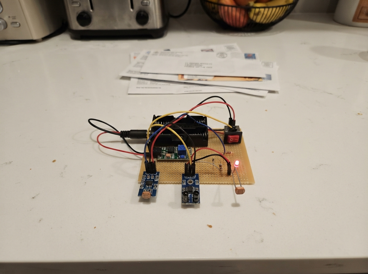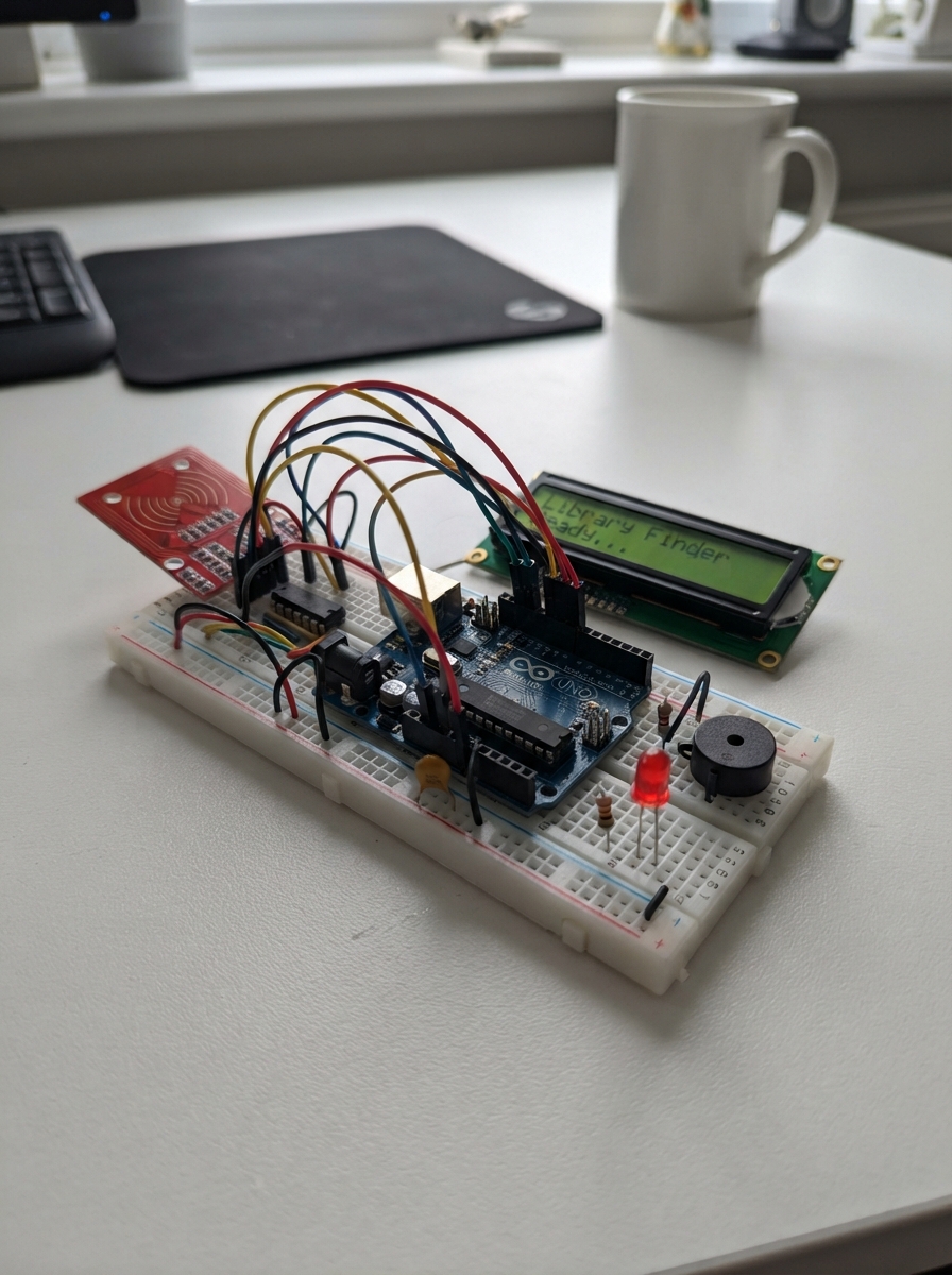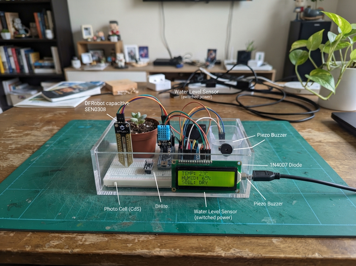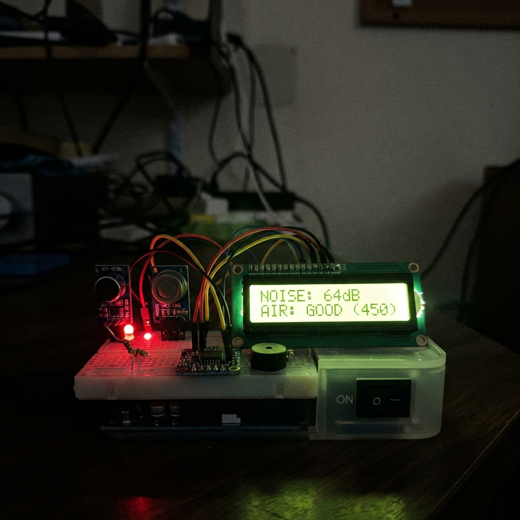
This classroom noise and air quality monitor combines sound and gas sensors with a real-time clock to track environmental conditions on a 16x2 LCD display. The system uses an Arduino Uno to read analog measurements from a KY-038 sound sensor and MQ135 air quality sensor, then displays the results alongside precise timestamps from an Adafruit DS3231 RTC module.
Builders will receive a complete wiring diagram, parts list, and Arduino firmware that logs sensor data with visual and audio alerts. Green and red status LEDs indicate normal or concerning conditions, while an active piezo buzzer provides audible notification when noise or air quality thresholds are exceeded. The guide covers the full assembly sequence from preparing the prototype through power distribution, sensor integration, and pre-power inspection.
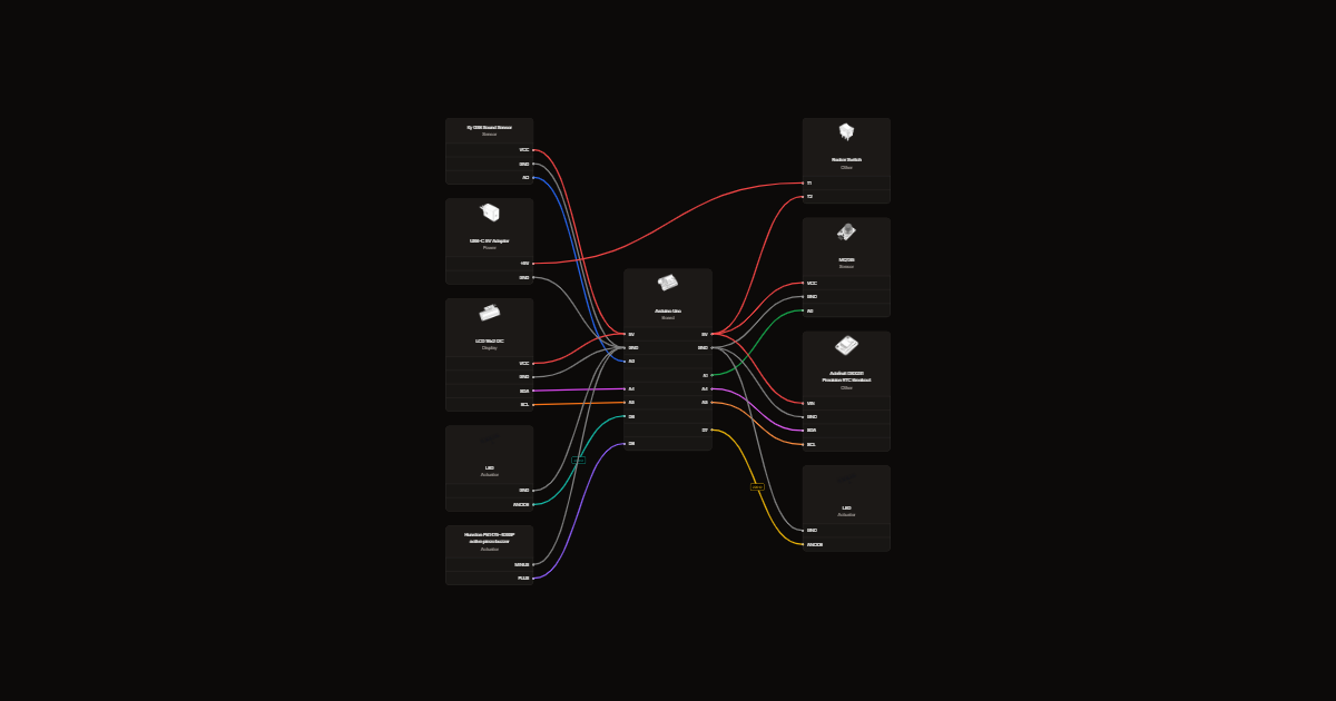
Wiring diagram
Gather all the parts
Assemble it in 7 steps
1. Prepare the unpowered prototype
Use an Uno R3, an 830-point breadboard, male-to-male and female-to-male jumper wires, and a USB cable matching the Uno USB-B socket. Disconnect all power before wiring.
2. Add the switched USB power path
Use a regulated 5 V USB supply rated at least 1 A and a USB power cable with accessible, insulated switch terminals. Connect its positive conductor through the two-terminal rocker switch to the Uno USB-B power input. Leave USB ground continuous. Power the modules from Uno 5V, never VIN.
- Do not connect the external supply while computer USB is connected. Do not modify a mains cable. Insulate switch terminals and verify polarity.
3. Distribute power and connect sensors
Connect Uno 5V and GND to breadboard rails. Connect sound VCC and gas VCC to 5V, and both GND pins to ground. Sound AO goes to A0; gas A0 goes to A1. Leave both digital outputs disconnected. Bridge split breadboard rails if needed.
- The MQ-135 heater becomes hot; keep it away from fingers and flammable materials.
4. Connect the shared display and clock bus
LCD VCC and RTC VIN go to 5V; both GND pins go to ground. Both SDA pins go to A4 for data and both SCL pins to A5 for clock. Leave RTC SQW, 32K, RST and BAT disconnected. Use the selected non-charging Adafruit DS3231 breakout; no battery is required while powered.
- Adjust the LCD backpack contrast screw if characters are invisible.
5. Connect the two status lights
Connect D6 through its own 220-ohm resistor to the green LED long leg. Connect D7 through the second 220-ohm resistor to the red LED long leg. Both short legs go to ground.
6. Connect the specified low-current buzzer
Connect the PB1475-40S5P positive terminal to D8 and negative terminal to GND. Mount it away from the microphone to reduce acoustic feedback.
- Only use the specified active piezo buzzer rated at maximum 10 mA. Higher-current or magnetic buzzers need a transistor driver and cannot be substituted directly.
7. Inspect before powering
Check every wire against the pin table. Confirm the two LED resistors, common ground, correct module polarity and no shorts between power rails. Place the gas sensor where classroom air can reach it.
- This prototype is not a certified gas alarm or health instrument. Do not use it to decide whether a room is safe.
Review all connections
1. Connections between "sound" and "Arduino"
2. Connections between "gas" and "Arduino"
3. Connections between "lcd" and "Arduino"
4. Connections between "rtc" and "Arduino"
5. Connections between "rg" and "Arduino"
6. Connections between "green" and "Arduino"
7. Connections between "rr" and "Arduino"
8. Connections between "red" and "Arduino"
9. Connections between "buzzer" and "Arduino"
10. Connections between "supply" and "Arduino"
11. Connections between "switch" and "Arduino"
Deploy the firmware
#include <Arduino.h>
#include <Wire.h>
#include <LiquidCrystal_I2C.h>
#include <RTClib.h>
// Raw ADC counts: these are demonstration settings, NOT dB, ppm or AQI.
const uint8_t SOUND_PIN=A0, GAS_PIN=A1, GREEN_PIN=6, RED_PIN=7, BUZZER_PIN=8;
const uint16_t NOISE_HIGH=60, NOISE_LOW=40;
const uint16_t AIR_HIGH=450, AIR_LOW=400;
const unsigned long WARMUP_MS=300000UL; // Increase until gas readings stabilize.
const bool SET_RTC=false; // Set true for ONE deployment, then restore false.
// Edit local date/time before setting SET_RTC. Deploy promptly.
const uint16_t RTC_YEAR=2026;
const uint8_t RTC_MONTH=11, RTC_DAY=18, RTC_HOUR=9, RTC_MINUTE=0, RTC_SECOND=0;
LiquidCrystal_I2C lcd(0x27,16,2);
RTC_DS3231 rtc;
bool rtcOK=false, clockValid=false, noisy=false, poor=false, buzzing=false;
uint16_t noise=0, air=0, sampleMin=1023, sampleMax=0;
uint8_t highWindows=0, lowWindows=0;
unsigned long windowStart=0, lastGas=0, lastDisplay=0, lastLog=0, buzzEnded=0;
char previous[2][17]={{0},{0}};
void showLine(uint8_t row,const char *text){
  char padded[17]; memset(padded,' ',16); padded[16]=0;
  size_t n=strlen(text); if(n>16)n=16; memcpy(padded,text,n);
  if(strcmp(previous[row],padded)!=0){lcd.setCursor(0,row);lcd.print(padded);strcpy(previous[row],padded);}
}
void setup(){
  pinMode(GREEN_PIN,OUTPUT); pinMode(RED_PIN,OUTPUT); pinMode(BUZZER_PIN,OUTPUT);
  digitalWrite(BUZZER_PIN,LOW); Serial.begin(9600); Wire.begin();
  lcd.init(); lcd.backlight(); rtcOK=rtc.begin();
  if(rtcOK){if(SET_RTC)rtc.adjust(DateTime(RTC_YEAR,RTC_MONTH,RTC_DAY,RTC_HOUR,RTC_MINUTE,RTC_SECOND));clockValid=!rtc.lostPower();}
  air=analogRead(GAS_PIN); windowStart=millis();
  Serial.println(F("Smart Classroom Noise and Air Quality Monitor"));
  Serial.println(F("Raw counts only. Set RTC and calibrate thresholds before use."));
}
void loop(){
  unsigned long t=millis(); bool warming=t<WARMUP_MS;
  // Short alert chirp every 3 seconds; exclude its sound and 200 ms ring-down.
  bool alarm=noisy||poor;
  bool wantBuzz=alarm && (t%3000UL<150UL);
  if(buzzing&&!wantBuzz)buzzEnded=t;
  buzzing=wantBuzz; digitalWrite(BUZZER_PIN,buzzing?HIGH:LOW);
  static bool sampling=false;
  bool maySample=!buzzing && t-buzzEnded>=200UL;
  if(!maySample){sampling=false;sampleMin=1023;sampleMax=0;windowStart=t;}
  else {
    if(!sampling){sampling=true;windowStart=t;}
    uint16_t s=analogRead(SOUND_PIN); if(s<sampleMin)sampleMin=s;if(s>sampleMax)sampleMax=s;
    if(t-windowStart>=50UL){
      noise=sampleMax-sampleMin;sampleMin=1023;sampleMax=0;windowStart=t;
      if(noise>=NOISE_HIGH){if(highWindows<10)highWindows++;lowWindows=0;}
      else if(noise<=NOISE_LOW){if(lowWindows<20)lowWindows++;highWindows=0;}
      else {highWindows=0;lowWindows=0;}
      if(highWindows>=10)noisy=true; if(lowWindows>=20)noisy=false;
    }
  }
  if(t-lastGas>=200UL){lastGas=t; air=(uint32_t(air)*7+analogRead(GAS_PIN))/8;
    if(!warming){if(air>=AIR_HIGH)poor=true;else if(air<=AIR_LOW)poor=false;}}
  alarm=noisy||poor;
  digitalWrite(RED_PIN,alarm?HIGH:LOW);
  digitalWrite(GREEN_PIN,(!alarm&&!warming&&clockValid)?HIGH:LOW);
  if(t-lastDisplay>=250UL){lastDisplay=t;char line[17];
    if((t/3000UL)%2==0){
      const char *status=noisy&&poor?"NOISE + AIR!":noisy?"HIGH NOISE!":poor?"POOR AIR!":warming?"AIR WARMUP":!clockValid?"SET RTC TIME":"NORMAL";
      showLine(0,status);snprintf(line,sizeof(line),"N:%3u A:%4u",noise,air);showLine(1,line);
    }else if(clockValid){DateTime d=rtc.now();snprintf(line,sizeof(line),"%04u-%02u-%02u",d.year(),d.month(),d.day());showLine(0,line);
      snprintf(line,sizeof(line),"%02u:%02u:%02u %s",d.hour(),d.minute(),d.second(),alarm?"WARN":"");showLine(1,line);
    }else{showLine(0,rtcOK?"RTC needs time":"RTC not found");showLine(1,"See setup notes");}}
  if(t-lastLog>=1000UL){lastLog=t;Serial.print(F("Noise p-p="));Serial.print(noise);Serial.print(F(" Air raw="));Serial.print(air);Serial.print(F(" Warmup="));Serial.print(warming);Serial.print(F(" Noise alarm="));Serial.print(noisy);Serial.print(F(" Air alarm="));Serial.println(poor);}
}
Remix this project
Make it yours in one click
Open a full copy of this project in your own Schematik workspace, diagram, code, parts, and assembly steps included. Swap the sensor, add features, or redesign the whole thing with AI. The author's original stays untouched.