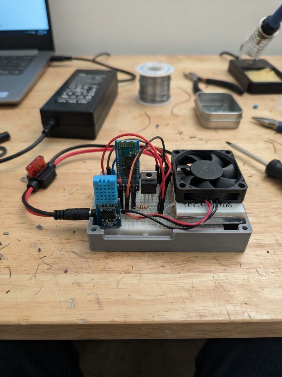
This project monitors humidity levels and triggers active cooling when conditions indicate rust risk, sending alerts via Bluetooth to a connected device. The system uses a DHT11 sensor to continuously measure ambient humidity and temperature, then activates a Peltier cooling module through a logic-level MOSFET when humidity climbs into the danger zone. The guide includes a complete wiring diagram showing how to safely integrate the high-current Peltier module with proper fusing and voltage protection for the Bluetooth module, plus the Arduino firmware that handles DHT11 sensor communication and sends real-time data over Bluetooth.
Builders will receive step-by-step assembly instructions for constructing the cold plate and condensation drain, wiring the humidity sensor to the Arduino, protecting the HC-05 Bluetooth module with a voltage divider, and building the high-current switch circuit. A separate 12V power adapter supplies the Peltier and cooling fan, keeping high currents away from the Arduino while a fused connection ensures safe operation. The complete parts list and firmware are included to get the system monitoring and alerting immediately.
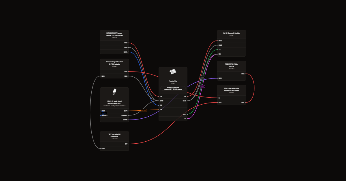
Wiring diagram
Gather all the parts
Assemble it in 5 steps
1. Build the cold plate and drain
Clamp the TEC1-12706 between a cold aluminium plate and a large hot-side heatsink using thermal paste. Mount the fan on the hot-side heatsink. Put the cold plate inside a small closed storage box and the hot heatsink outside. Collect water in a tray with a drain outside the box.
- Never power the Peltier without its heatsink and running fan. This prototype has no automatic hot-side temperature protection; operate under supervision only.
- Keep condensed water away from stored metal and all electronics. It is not a room dehumidifier.
2. Wire the humidity sensor
Use the DFR0067 three-wire DHT11 breakout. VCC to Uno 5V, GND to GND, DATA to D2 (humidity and temperature data). Place it away from the cold plate and water.
3. Wire Bluetooth with voltage protection
Use the HC-05 breakout with onboard regulator, not the bare 3.3V radio. Vcc to 5V, GND to GND, TX to D10 (data into Uno). D11 goes through the 1 kOhm resistor to RX; connect the 2 kOhm resistor from RX to GND. This lowers the outgoing 5V signal to about 3.3V. Leave KEY and STATE unconnected.
4. Build the high-current switch
D6 goes through the 220 Ohm resistor to MOSFET gate; 10 kOhm goes between gate and source to keep it off at startup. Source goes to shared ground. Drain goes to Peltier negative. Identify gate, drain and source from the IRLZ44N datasheet before connecting; do not guess leg order. Mount the MOSFET on a small insulated heatsink.
- Peltier current must use screw terminals and at least 18 AWG wire, never a solderless breadboard or Uno pins. The MOSFET metal tab is electrically connected to drain.
5. Connect the separate power adapter
With power unplugged, connect adapter positive through the 7.5A fuse to Peltier positive and fan 12V. Adapter negative connects to fan ground, MOSFET source and Uno GND. Leave fan PWM and TACH disconnected so it runs at full speed. Power the Uno through USB separately.
- Never connect 12V to the Uno 5V pin. Use a factory-enclosed 12V 10A adapter; do not work on mains wiring.
Review all connections
1. Connections between "humidity" and "Arduino"
2. Connections between "bluetooth" and "Arduino"
3. Connections between "divider_top" and "Arduino"
4. Connections between "divider_bottom" and "Arduino"
5. Connections between "gate_series" and "Arduino"
6. Connections between "gate_pull" and "Arduino"
7. Connections between "switch" and "Arduino"
8. Connections between "supply" and "Arduino"
9. Connections between "fuse" and "Arduino"
10. Connections between "cooler" and "Arduino"
11. Connections between "fan" and "Arduino"
Deploy the firmware
#include <Arduino.h>
#include <SoftwareSerial.h>
SoftwareSerial phone(10,11);
const uint8_t SENSOR=2, COOLER=6;
bool risk=false, running=false;
uint8_t highCount=0,lowCount=0;
unsigned long lastRead=0,started=0,pauseUntil=0;
// DHT11: 18 ms start low, 80 us response low/high, 40 timed data bits.
bool waitLevel(uint8_t level, unsigned int timeout) {
  unsigned long t=micros();
  while(digitalRead(SENSOR)==level) if(micros()-t>timeout)return false;
  return true;
}
bool readDht(float &rh,float &tc){
  uint8_t b[5]={0};
  pinMode(SENSOR,OUTPUT);digitalWrite(SENSOR,LOW);delay(20);
  digitalWrite(SENSOR,HIGH);delayMicroseconds(30);pinMode(SENSOR,INPUT_PULLUP);
  noInterrupts();
  bool ok=waitLevel(HIGH,100)&&waitLevel(LOW,100)&&waitLevel(HIGH,100);
  for(uint8_t i=0;i<40&&ok;i++){
    ok=waitLevel(LOW,100);unsigned long t=micros();
    if(ok)ok=waitLevel(HIGH,100);
    b[i/8]=(b[i/8]<<1)|((micros()-t)>45 ? 1:0);
  }
  interrupts();
  if(!ok || uint8_t(b[0]+b[1]+b[2]+b[3])!=b[4])return false;
  rh=b[0]+b[1]*0.1f;tc=b[2]+b[3]*0.1f;
  return rh>=20&&rh<=90&&tc>=0&&tc<=50;
}
void output(float rh,float tc,bool valid){
  // CSV: DATA,humidity,temperature,risk,cooler -- one line every 3 seconds.
  phone.print(valid?F("DATA,"):F("ERROR,"));phone.print(rh,1);phone.print(',');
  phone.print(tc,1);phone.print(',');phone.print(risk?1:0);phone.print(',');phone.println(running?1:0);
  Serial.print(valid?F("Humidity %: "):F("SENSOR ERROR: "));Serial.print(rh);Serial.print(F(" temperature C: "));Serial.println(tc);
}
void setup(){digitalWrite(COOLER,LOW);pinMode(COOLER,OUTPUT);Serial.begin(9600);phone.begin(9600);}
void loop(){
  unsigned long now=millis();
  if(now-lastRead<3000)return;lastRead=now;
  float rh=0,tc=0;bool valid=readDht(rh,tc);
  if(!valid){running=false;highCount=lowCount=0;digitalWrite(COOLER,LOW);output(rh,tc,false);return;}
  if(rh>=60){if(highCount<20)highCount++;lowCount=0;}else if(rh<=50){if(lowCount<20)lowCount++;highCount=0;}else{highCount=lowCount=0;}
  if(highCount>=20)risk=true;
  if(lowCount>=20)risk=false;
  if(running&&(!risk||now-started>=600000UL)){running=false;pauseUntil=now+120000UL;}
  if(!running&&risk&&(pauseUntil==0||(long)(now-pauseUntil)>=0)){running=true;started=now;}
  digitalWrite(COOLER,running?HIGH:LOW);output(rh,tc,true);
}
Remix this project
Make it yours in one click
Open a full copy of this project in your own Schematik workspace, diagram, code, parts, and assembly steps included. Swap the sensor, add features, or redesign the whole thing with AI. The author's original stays untouched.