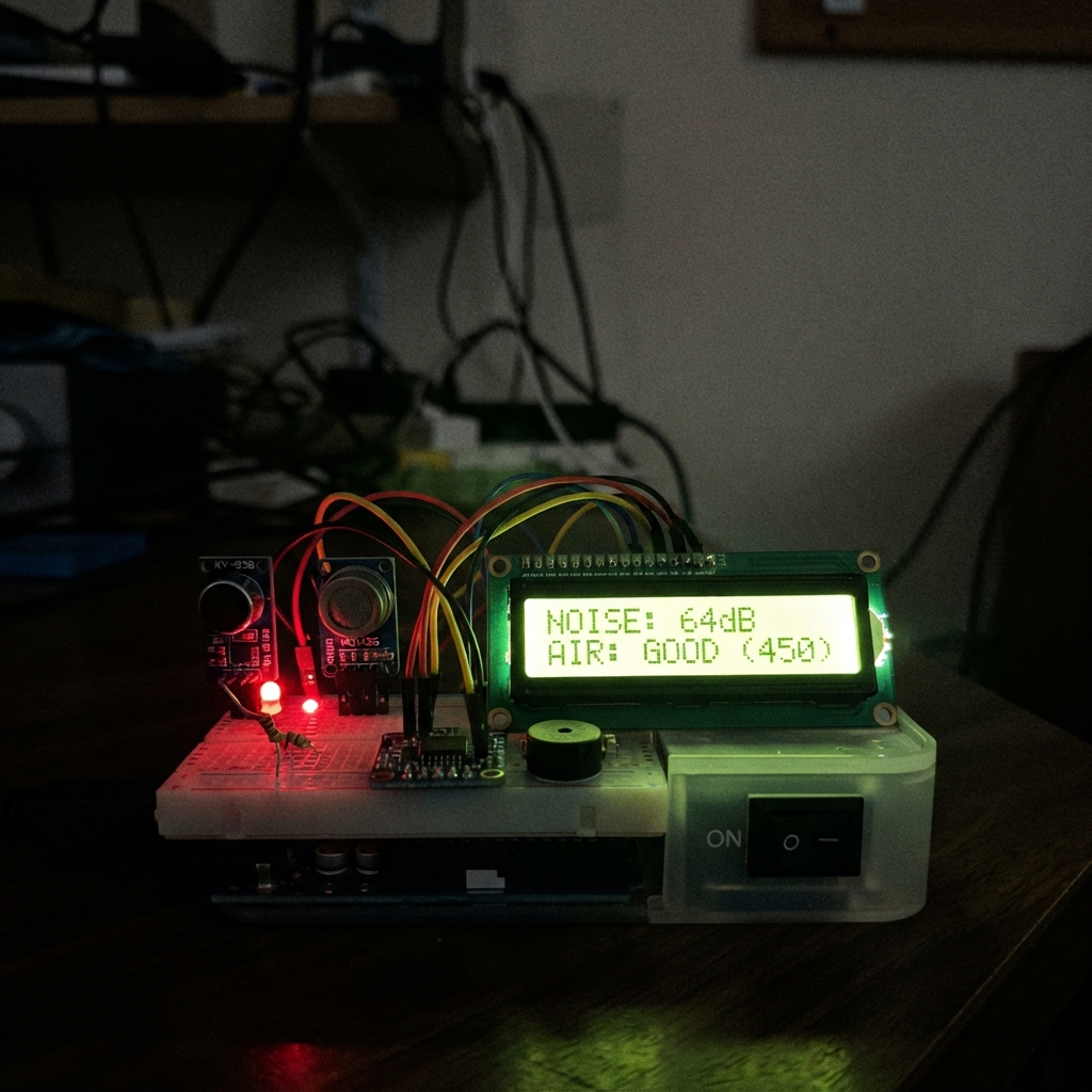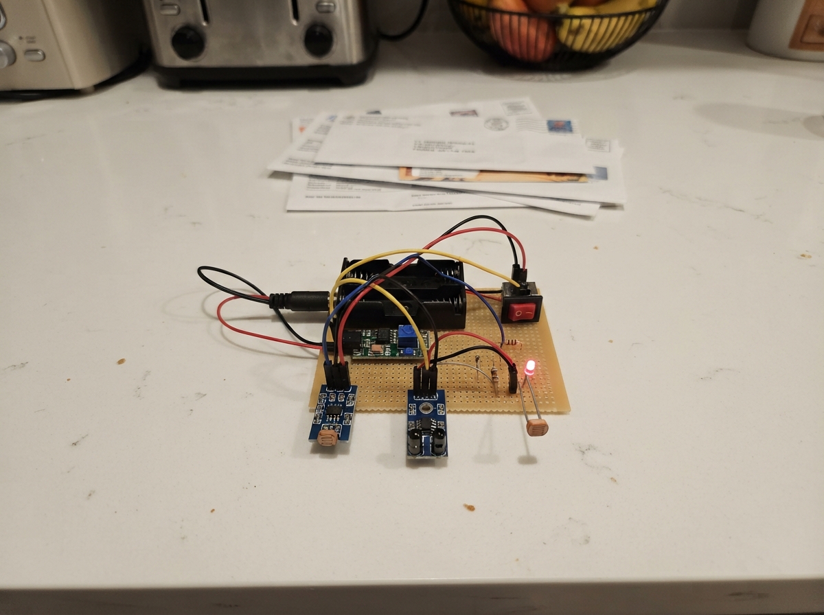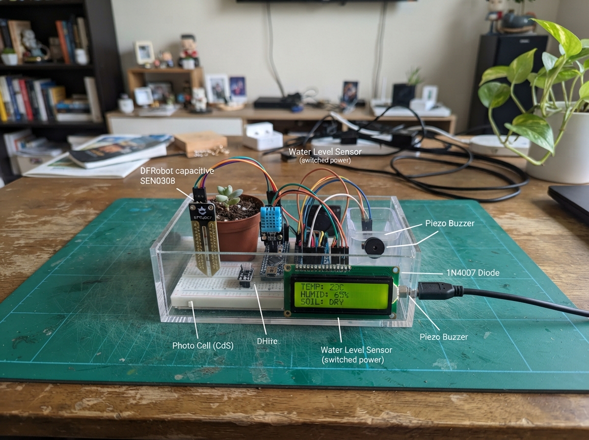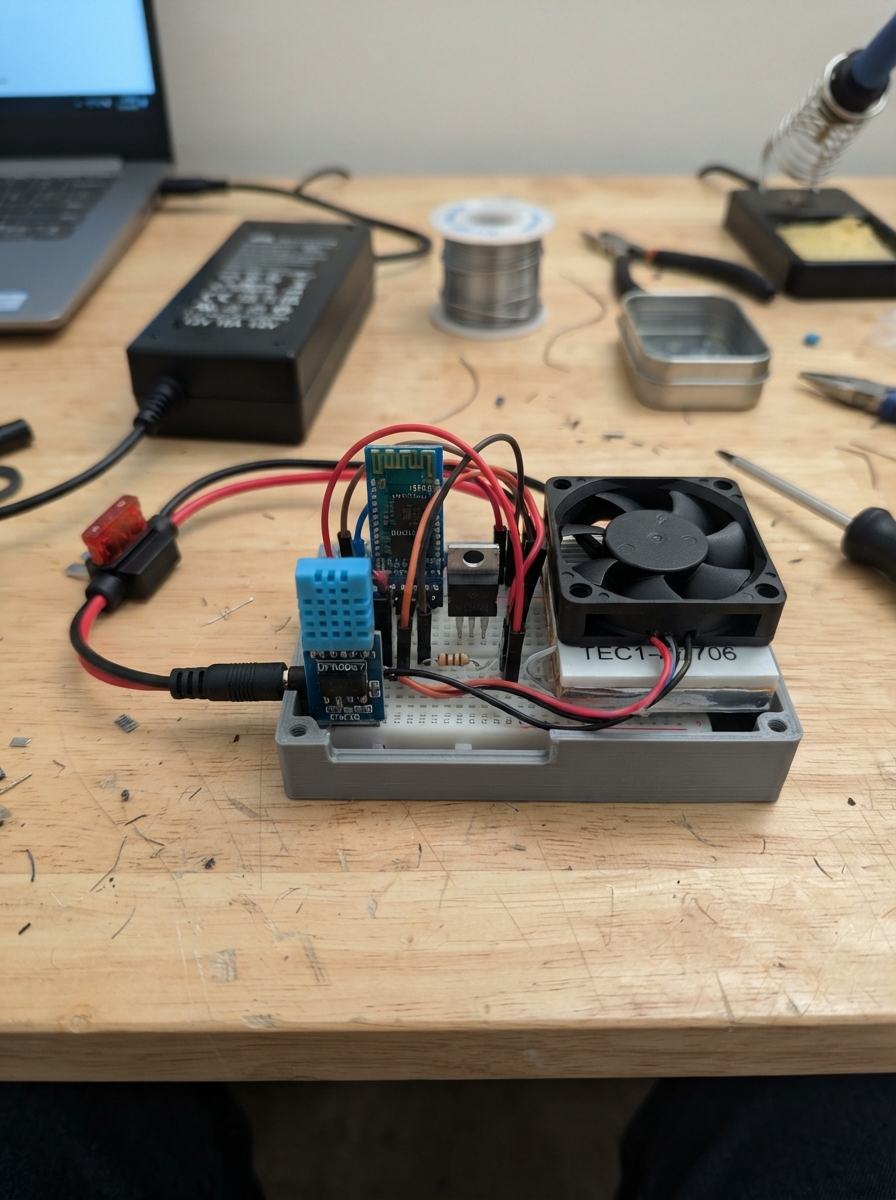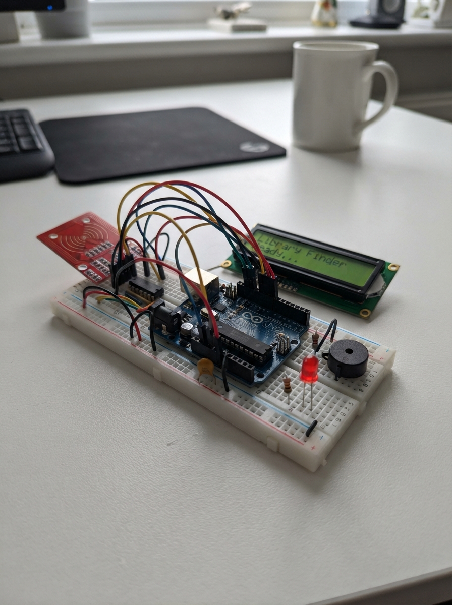
This project builds a smart library book finder that uses RFID technology to identify books and communicate their status to a user. An MFRC522 RFID reader detects book tags, while a 16x2 LCD display shows real-time information and a piezo buzzer provides audio feedback. The system connects to a PC application via serial communication to look up book locations and availability.
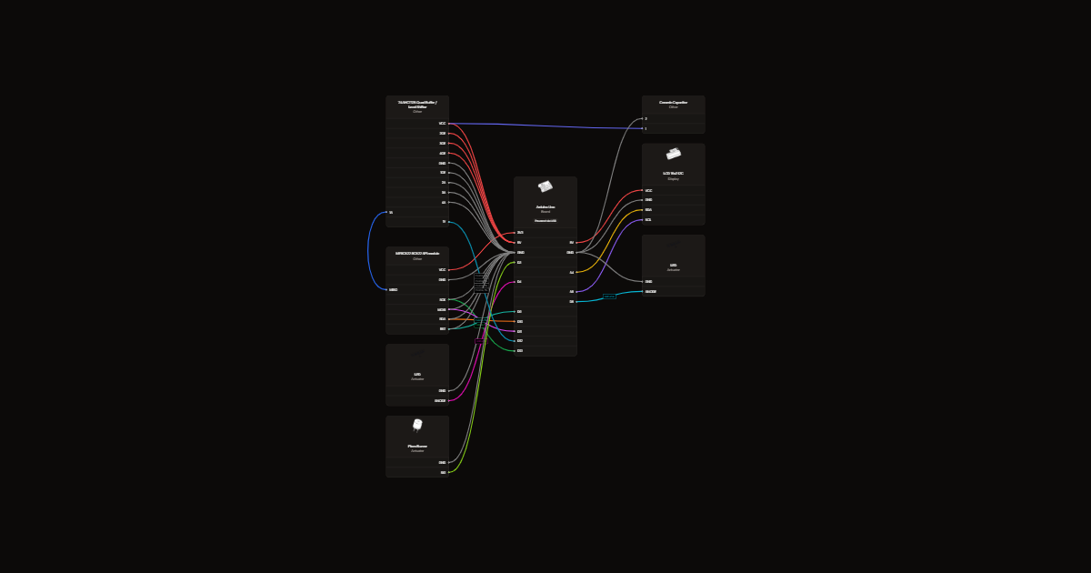
The guide provides a complete wiring diagram, parts list, and step-by-step assembly instructions for connecting the RFID reader, display, status LEDs, and buzzer to an Arduino Uno. Included firmware handles RFID scanning, serial communication with the host application, and display management, allowing makers to build a functional library management interface.
Wiring diagram
Gather all the parts
Assemble it in 5 steps
1. Prepare the unpowered breadboard
Unplug USB. Put the Uno beside an 830-point breadboard. Use short jumper wires and keep the reader antenna away from metal. Join all ground connections. Do not join the 5 V and 3.3 V rails.
2. Protect the reader inputs
For each of SCK, MOSI, SDA and RST, connect its Uno pin through a 1 kohm resistor to the reader input. Connect a 2 kohm resistor from that same input to ground. The wiring diagram shows each pair separately. Power the reader from Uno 3.3 V only. Leave IRQ unconnected if present.
- Direct 5 V power or logic can damage the RC522.
3. Raise the return signal safely
Place SN74AHCT125N across the centre channel. Pin 14 is 5 V and pin 7 is ground. Pin 1 goes to ground, reader MISO to pin 2, and pin 3 to D12. Pins 4, 10 and 13 go to 5 V; pins 5, 9 and 12 go to ground. Leave pins 6, 8 and 11 open. Place the 100 nF capacitor between pins 14 and 7.
4. Connect display and indicators
LCD VCC to 5 V, GND to ground, SDA to A4 and SCL to A5. D4 feeds the green LED through 330 ohm; D5 feeds the red LED through its own 330 ohm. LED short legs go to ground. Passive piezo connects D3 to ground.
5. Arrange the demonstration
Put the reader at the scanning station, display above it and LEDs beside it. Place one compatible passive tag inside each book cover and one on each shelf front. Start with two books and two shelves. Present only one tag at a time within a few centimetres, then remove it before the next scan. Use USB power from the laptop after checking all wires.
Review all connections
1. Connections between "reader" and "Arduino"
2. Connections between "lcd" and "Arduino"
3. Connections between "rg" and "Arduino"
4. Connections between "green" and "Arduino"
5. Connections between "rr" and "Arduino"
6. Connections between "red" and "Arduino"
7. Connections between "buzzer" and "Arduino"
8. Connections between "buffer" and "Arduino"
9. Connections between "bypass" and "Arduino"
10. Connections between "sck_top" and "Arduino"
11. Connections between "sck_bottom" and "Arduino"
12. Connections between "mosi_top" and "Arduino"
13. Connections between "mosi_bottom" and "Arduino"
14. Connections between "sda_top" and "Arduino"
15. Connections between "sda_bottom" and "Arduino"
16. Connections between "rst_top" and "Arduino"
17. Connections between "rst_bottom" and "Arduino"
Deploy the firmware
#include <Arduino.h>
#include <SPI.h>
#include <Wire.h>
#include <MFRC522.h>
#include <LiquidCrystal_I2C.h>
MFRC522 reader(10,9);
LiquidCrystal_I2C lcd(0x27,16,2);
char input[80], previous[33]=""; byte pos=0; bool overflow=false;
unsigned long lastHost=0; bool online=false;
void screen(const char *a,const char *b){
 char text[33]; memset(text,' ',32); text[32]=0;
 memcpy(text,a,min(strlen(a),(size_t)16)); memcpy(text+16,b,min(strlen(b),(size_t)16));
 if(strcmp(text,previous)==0)return;
 memcpy(previous,text,33);
 for(byte row=0;row<2;row++){lcd.setCursor(0,row);for(byte c=0;c<16;c++)lcd.write(text[row*16+c]);}
}
void command(){
 char *mode=strtok(input,"|"),*a=strtok(NULL,"|"),*b=strtok(NULL,"|");
 if(!mode)return; lastHost=millis(); online=true;
 if(!strcmp(mode,"PING"))return;
 digitalWrite(4,!strcmp(mode,"OK"));digitalWrite(5,!strcmp(mode,"WRONG"));
 if(!strcmp(mode,"WRONG"))tone(3,4000,700);
 if(a&&b)screen(a,b);
}
void setup(){
 Serial.begin(9600);pinMode(4,OUTPUT);pinMode(5,OUTPUT);pinMode(3,OUTPUT);
 Wire.begin();lcd.init();lcd.backlight();screen("SMART LIBRARY","Start PC app");
 SPI.begin();reader.PCD_Init();Serial.println(F("READY"));
 byte v=reader.PCD_ReadRegister(MFRC522::VersionReg);
 if(v==0||v==255){screen("Reader error","Check SPI wires");Serial.println(F("ERROR|READER"));}
}
void loop(){
 while(Serial.available()){char c=Serial.read();if(c=='\n'){input[pos]=0;if(!overflow)command();pos=0;overflow=false;}else if(c!='\r'){if(pos<79)input[pos++]=c;else overflow=true;}}
 if(online&&millis()-lastHost>6000){online=false;digitalWrite(4,LOW);digitalWrite(5,LOW);screen("PC disconnected","No verification");}
 if(reader.PICC_IsNewCardPresent()&&reader.PICC_ReadCardSerial()){
 Serial.print(F("TAG|"));for(byte i=0;i<reader.uid.size;i++){if(reader.uid.uidByte[i]<16)Serial.print('0');Serial.print(reader.uid.uidByte[i],HEX);}Serial.println();
 reader.PICC_HaltA();reader.PCD_StopCrypto1();
 }
}
Remix this project
Make it yours in one click
Open a full copy of this project in your own Schematik workspace, diagram, code, parts, and assembly steps included. Swap the sensor, add features, or redesign the whole thing with AI. The author's original stays untouched.