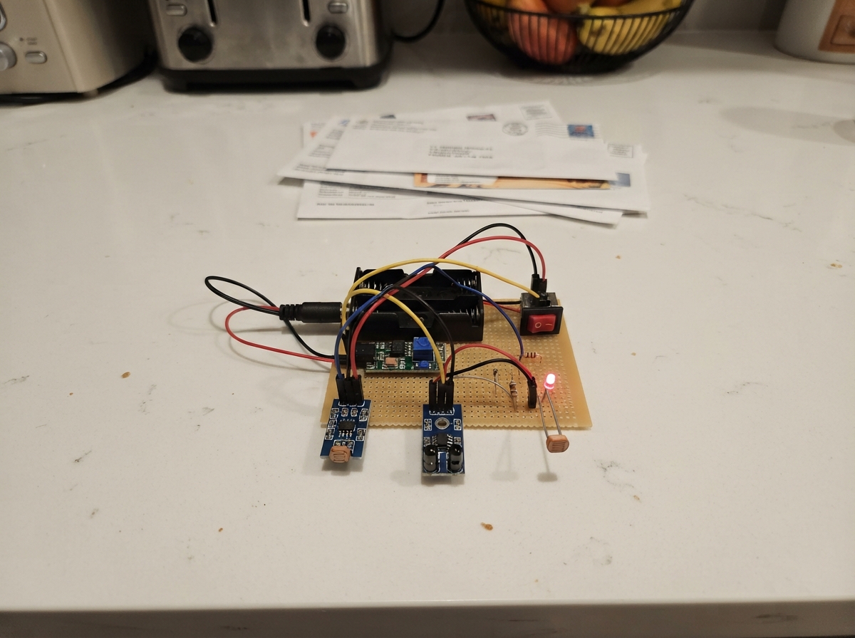
This project builds an intelligent street lighting system that automatically adjusts six LEDs based on ambient light and motion detection. The system uses an Arduino Uno to monitor a light sensor and three infrared motion detectors, controlling lighting zones that brighten to full brightness when motion is detected in darkness, then dim to a low level after the motion stops.
The guide provides a complete parts list, wiring diagram, and step-by-step assembly instructions for building the controller on stripboard. Firmware is included to handle the sensing logic, with adjustable thresholds for light sensitivity and motion hold times. The power supply uses eight AA batteries stepped down to 5V through a buck converter, with rocker switches for convenient on/off control.
Wiring diagram
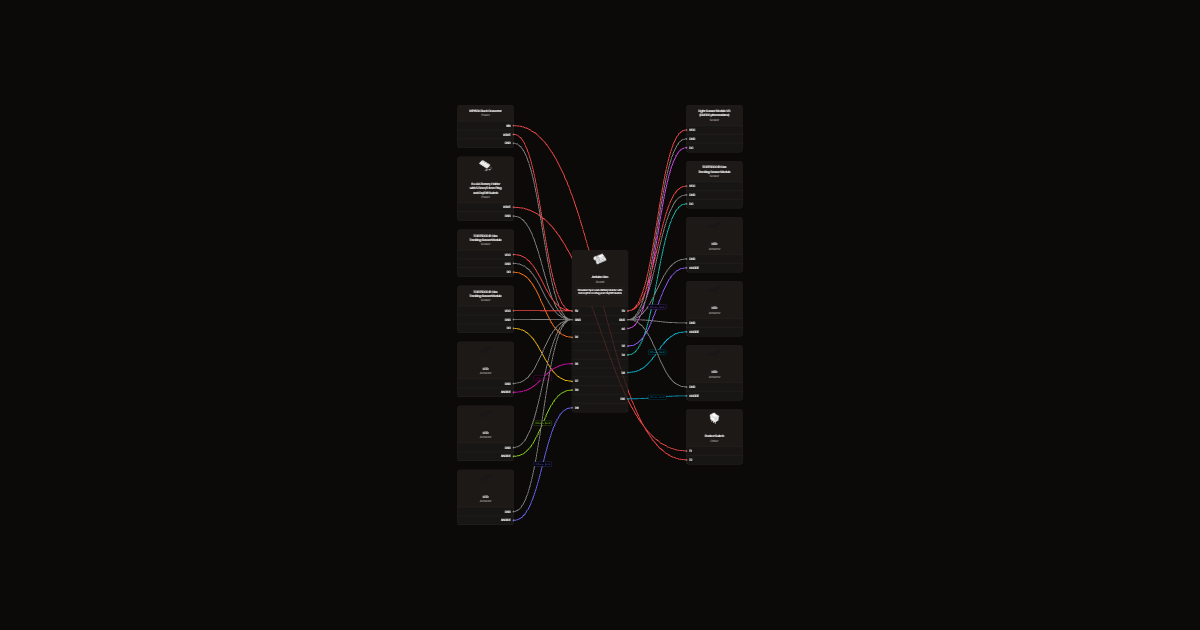
Gather all the parts
Assemble it in 6 steps
1. Prepare isolated stripboard tracks
Use one copper strip for 5 V and another for GND. Keep every sensor signal and LED output on separate isolated strips or insulated jumpers. Stripboard copper is on the underside; check continuity rather than trusting the top view.
- Cut tracks where needed. An uncut strip joining two outputs or joining 5 V to GND can damage the board.
2. Set the battery supply to 5 V
Use eight alkaline AA cells in the battery holder. Battery positive goes through the external rocker switch to buck VIN. Battery negative goes to buck GND. With the Uno and sensors disconnected, measure buck VOUT to GND and adjust it to 5.0 V. Turn power off before continuing.
- Do not connect 12 V to the Uno 5V pin. Do not charge alkaline cells. Keep exposed battery wires from touching.
3. Connect the common power buses
Buck VOUT goes to the 5 V strip and Uno 5V pin. Buck GND goes to the GND strip and Uno GND. Both strips also feed VCC and GND on all four sensor modules. Leave unused AO pins disconnected.
- Disconnect buck VOUT from the 5 V strip before plugging USB into the Uno; never feed USB and external 5 V together.
4. Wire the sensor signals
IR1 DO goes to D2, IR2 DO to D4, and IR3 DO to D7 (detection signals). LDR DO goes to A0 (day/night signal); A0 is used as a digital input here. The selected IR modules label the diagram's OUT pin DO.
5. Connect six small street lights
Connect D3, D5, D6, D9, D10 and D11 to R1 through R6 respectively. Each 220 ohm resistor then connects to its LED's long positive leg. Each short negative leg connects to GND. Pair lights 1–2 with IR1, 3–4 with IR2, and 5–6 with IR3.
- Only small individual LEDs belong on these outputs. LED strips or 12 V lamps require separate drivers and must not connect directly.
6. Adjust the sensing thresholds
Keep the LDR away from the six LEDs so it measures room light. Adjust its trimmer until DO changes between bright and dark. Position the TCRT5000 modules about 1–25 mm from a model target; adjust each trimmer so a low-reflectance target gives LOW and the clear condition gives HIGH. At night each detected target brightens its pair for five seconds after it leaves.
- These are close-range model sensors, not outdoor traffic sensors. If your existing IR modules report detection as HIGH, change IR_DETECTED_LEVEL in the firmware to HIGH.
Review all connections
1. Connections between "battery" and "Arduino"
2. Connections between "switch" and "Arduino"
3. Connections between "buck" and "Arduino"
4. Connections between "ldr" and "Arduino"
5. Connections between "ir1" and "Arduino"
6. Connections between "ir2" and "Arduino"
7. Connections between "ir3" and "Arduino"
8. Connections between "r1" and "Arduino"
9. Connections between "led1" and "Arduino"
10. Connections between "r2" and "Arduino"
11. Connections between "led2" and "Arduino"
12. Connections between "r3" and "Arduino"
13. Connections between "led3" and "Arduino"
14. Connections between "r4" and "Arduino"
15. Connections between "led4" and "Arduino"
16. Connections between "r5" and "Arduino"
17. Connections between "led5" and "Arduino"
18. Connections between "r6" and "Arduino"
19. Connections between "led6" and "Arduino"
Deploy the firmware
#include <Arduino.h>
const uint8_t IR_PINS[3] = {2, 4, 7};
const uint8_t LED_PINS[6] = {3, 5, 6, 9, 10, 11};
const uint8_t LIGHT_PIN = A0;
// Selected LM393 LDR module: HIGH = dark. Selected IR modules:
// LOW = low-reflectance target. Change this for opposite-output modules.
const uint8_t IR_DETECTED_LEVEL = LOW;
const uint8_t DIM_LEVEL = 45;
const uint32_t HOLD_MS = 5000;
uint32_t lastDetection[3] = {};
bool holding[3] = {};
uint8_t previous[6] = {};
bool dark = false, candidateDark = false;
uint32_t candidateSince = 0;
void setup() {
  pinMode(LIGHT_PIN, INPUT);
  for (uint8_t i=0;i<3;i++) pinMode(IR_PINS[i], INPUT_PULLUP);
  for (uint8_t i=0;i<6;i++) { pinMode(LED_PINS[i], OUTPUT); analogWrite(LED_PINS[i],0); }
  candidateDark = digitalRead(LIGHT_PIN) == HIGH;
  candidateSince = millis();
}
void loop() {
  const uint32_t now = millis();
  const bool readingDark = digitalRead(LIGHT_PIN) == HIGH;
  if (readingDark != candidateDark) { candidateDark=readingDark; candidateSince=now; }
  if (now-candidateSince >= 500) dark=candidateDark;
  for (uint8_t zone=0; zone<3; zone++) {
    if (!dark) holding[zone]=false;
    else if (digitalRead(IR_PINS[zone]) == IR_DETECTED_LEVEL) {
      lastDetection[zone]=now; holding[zone]=true;
    } else if (holding[zone] && now-lastDetection[zone]>=HOLD_MS) holding[zone]=false;
    const uint8_t level = !dark ? 0 : holding[zone] ? 255 : DIM_LEVEL;
    for (uint8_t j=0;j<2;j++) {
      const uint8_t i=zone*2+j;
      if (previous[i]!=level) { analogWrite(LED_PINS[i],level); previous[i]=level; }
    }
  }
  delay(5);
}
Remix this project
Make it yours in one click
Open a full copy of this project in your own Schematik workspace, diagram, code, parts, and assembly steps included. Swap the sensor, add features, or redesign the whole thing with AI. The author's original stays untouched.