Community project
Create A Simple Copanion Which Uses Grok Humalik
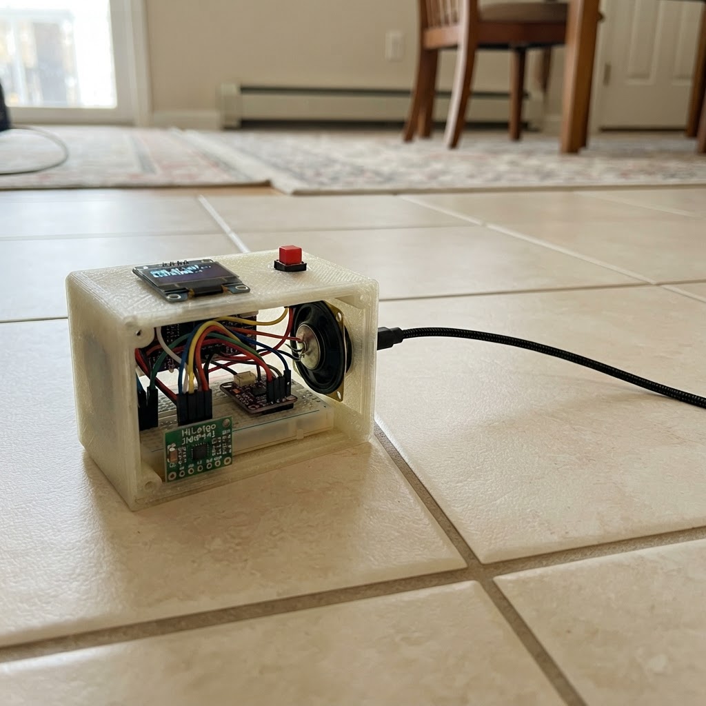
Build an interactive voice companion powered by the ESP32 that listens to your voice, processes it through Grok AI, and speaks back responses. This project combines audio input from an I²S microphone, real-time display feedback on an OLED screen, and audio output through a Class-D amplifier and speaker to create a conversational device that feels alive and responsive.
This guide provides a complete wiring diagram, parts list, and step-by-step assembly instructions to connect the microphone module, amplifier, display, and push button to your ESP32. The included firmware handles WiFi connectivity, audio capture and playback, and communication with a relay server that keeps your API keys secure while interfacing with Grok and text-to-speech services.
Wiring diagram

Gather all the parts
Assemble it in 6 steps
1. Set up the power rails
Place the ESP32-S3 board, microphone, amplifier, display, button, and speaker on a breadboard or beside it. Use red wires for the 3.3 V rail, red wires for the 5 V rail, and black wires for ground. Connect the microphone VDD and display VCC to 3V3 (power). Connect the amplifier VIN to 5V (power). Connect the microphone GND, display GND, amplifier GND, and button GND to GND (ground).
- The 5 V pin is used only for the amplifier supply; all ESP32-S3 signal wires are still safe 3.3 V signals.
- Keep every black ground wire connected to the same ground rail so the modules can understand the board's signals.
- Do not connect the microphone or display VCC to 5 V — swapped or excessive power can damage those small modules.
- Unplug USB power before moving wires.
2. Wire the little face screen
On the SSD1306 screen, connect SDA to GPIO8 (data) and SCL to GPIO9 (clock). Its VCC and GND should already be on the 3.3 V and ground rails from the first step.
- Most 0.96-inch SSD1306 screens label their four pins GND, VCC, SCL, SDA; read the printing on your own screen rather than relying on its physical pin order.
- Make sure VCC and GND are not swapped — swapped power can damage the screen.
3. Wire the microphone
Connect the INMP441 SCK pin to GPIO14 (sound timing), WS to GPIO15 (sound timing), and SD to GPIO5 (microphone signal). Connect the INMP441 L/R pin to GND (channel choice). Its VDD and GND should already be on 3V3 and GND.
- Use short wires for the three microphone signal connections; this makes the recorded voice less likely to pick up electrical noise.
- The INMP441 is a 3.3 V part. Never connect its VDD pin to the 5 V amplifier rail.
4. Wire the speaker amplifier and speaker
Connect the MAX98357A BCLK pin to GPIO17 (sound timing), LRC to GPIO18 (sound timing), and DIN to GPIO6 (sound signal). Connect the amplifier SPK+ terminal to the speaker POS terminal (speaker positive), and SPK- to the speaker NEG terminal (speaker negative). Its VIN and GND should already be on 5V and GND.
- The speaker has only two wires. Keep both speaker wires between the speaker and the amplifier; do not connect either speaker wire to board ground.
- If the sound is quiet, use a short, sturdy USB cable because the amplifier draws extra current while speaking.
- Do not attach the speaker directly to an ESP32-S3 GPIO pin — that can damage the board pin and will not make usable sound.
- Do not join SPK- to ground; the amplifier drives both speaker terminals.
5. Add the talk button
Connect one button leg to GPIO4 (signal) and the other button leg to GND (ground). If your tactile button has four legs, the two legs on each same side are already joined inside; use one leg from each opposite side.
- The firmware uses the ESP32-S3's built-in pull-up, so no separate resistor is needed for this button.
- Before closing a case, press the button while powered: the face should change to the listening expression for three seconds.
- Do not use GPIO4 as a power connection; it is only the button signal wire.
6. Connect and test the companion
Check every power wire one more time, then plug the ESP32-S3 into USB. The normal face should say “Press to talk.” After you set the Wi-Fi name, Wi-Fi password, and relay address in the firmware, press the button, speak during the three-second listening period, and wait for the spoken reply.
- Keep the microphone a few inches away from the speaker so the companion records your voice instead of its own reply.
- The relay must accept the raw 16 kHz mono audio request and return raw signed 16-bit, 16 kHz mono audio; it is the private bridge to Humalike, Grok, and ElevenLabs.
- Never place private Humalike, Grok, or ElevenLabs keys in this board firmware. Keep them only in the secure relay.
Review all connections
1. Connections between "mic" and "ESP32"
2. Connections between "amp" and "ESP32"
3. Connections between "display" and "ESP32"
4. Connections between "talk_button" and "ESP32"
Deploy the firmware
#include <Arduino.h>
#include <WiFi.h>
#include <HTTPClient.h>
#include <Wire.h>
#include <Adafruit_GFX.h>
#include <Adafruit_SSD1306.h>
#include <driver/i2s.h>
// Put the Wi-Fi details and the HTTPS address of YOUR relay here.
// The relay keeps the Humalike, Grok, and ElevenLabs keys private.
// Hoisted type definitions
enum CompanionState { READY, LISTENING, THINKING, SPEAKING, ERROR_STATE };
// Forward declarations
void drawFace(CompanionState state, const char *caption);
void connectWiFi();
void setupAudio();
bool sendAndPlay(int16_t *samples);
const char *WIFI_SSID = "YOUR_WIFI_NAME";
const char *WIFI_PASSWORD = "YOUR_WIFI_PASSWORD";
const char *RELAY_URL = "https://your-relay.example.com/companion";
constexpr int BUTTON_PIN = 4;
constexpr int OLED_SDA_PIN = 8;
constexpr int OLED_SCL_PIN = 9;
constexpr int MIC_BCLK_PIN = 14;
constexpr int MIC_LRCLK_PIN = 15;
constexpr int MIC_DATA_PIN = 5;
constexpr int AMP_BCLK_PIN = 17;
constexpr int AMP_LRCLK_PIN = 18;
constexpr int AMP_DATA_PIN = 6;
constexpr uint32_t SAMPLE_RATE = 16000;
constexpr size_t RECORD_SECONDS = 3;
constexpr size_t SAMPLE_COUNT = SAMPLE_RATE * RECORD_SECONDS;
Adafruit_SSD1306 display(128, 64, &Wire, -1);
CompanionState shownState = ERROR_STATE;
void drawFace(CompanionState state, const char *caption) {
if (state == shownState && state != ERROR_STATE) return;
shownState = state;
display.clearDisplay();
display.drawRoundRect(2, 2, 124, 45, 8, SSD1306_WHITE);
if (state == LISTENING) {
display.fillCircle(38, 23, 7, SSD1306_WHITE);
display.fillCircle(90, 23, 7, SSD1306_WHITE);
display.drawCircle(64, 34, 10, SSD1306_WHITE);
} else if (state == THINKING) {
display.drawCircle(38, 23, 4, SSD1306_WHITE);
display.fillCircle(64, 23, 5, SSD1306_WHITE);
display.fillCircle(90, 23, 7, SSD1306_WHITE);
display.drawLine(48, 35, 80, 35, SSD1306_WHITE);
} else if (state == SPEAKING) {
display.fillCircle(38, 23, 6, SSD1306_WHITE);
display.fillCircle(90, 23, 6, SSD1306_WHITE);
display.drawRoundRect(51, 29, 26, 12, 6, SSD1306_WHITE);
} else if (state == ERROR_STATE) {
display.drawLine(31, 16, 45, 30, SSD1306_WHITE);
display.drawLine(45, 16, 31, 30, SSD1306_WHITE);
display.drawLine(83, 16, 97, 30, SSD1306_WHITE);
display.drawLine(97, 16, 83, 30, SSD1306_WHITE);
display.drawLine(43, 38, 85, 38, SSD1306_WHITE);
} else {
display.fillCircle(38, 23, 6, SSD1306_WHITE);
display.fillCircle(90, 23, 6, SSD1306_WHITE);
display.drawLine(46, 34, 54, 40, SSD1306_WHITE);
display.drawLine(54, 40, 64, 42, SSD1306_WHITE);
display.drawLine(64, 42, 74, 40, SSD1306_WHITE);
display.drawLine(74, 40, 82, 34, SSD1306_WHITE);
}
display.setTextSize(1);
display.setTextColor(SSD1306_WHITE);
display.setCursor(6, 53);
display.print(caption);
display.display();
}
void connectWiFi() {
if (WiFi.status() == WL_CONNECTED) return;
drawFace(THINKING, "Joining Wi-Fi...");
WiFi.mode(WIFI_STA);
WiFi.begin(WIFI_SSID, WIFI_PASSWORD);
const uint32_t started = millis();
while (WiFi.status() != WL_CONNECTED && millis() - started < 15000) {
delay(250);
}
}
void setupAudio() {
i2s_config_t micConfig = {};
micConfig.mode = (i2s_mode_t)(I2S_MODE_MASTER | I2S_MODE_RX);
micConfig.sample_rate = SAMPLE_RATE;
micConfig.bits_per_sample = I2S_BITS_PER_SAMPLE_32BIT;
micConfig.channel_format = I2S_CHANNEL_FMT_ONLY_LEFT;
micConfig.communication_format = I2S_COMM_FORMAT_I2S;
micConfig.intr_alloc_flags = ESP_INTR_FLAG_LEVEL1;
micConfig.dma_buf_count = 8;
micConfig.dma_buf_len = 128;
micConfig.use_apll = false;
micConfig.tx_desc_auto_clear = false;
micConfig.fixed_mclk = 0;
i2s_driver_install(I2S_NUM_0, &micConfig, 0, nullptr);
i2s_pin_config_t micPins = {};
micPins.bck_io_num = MIC_BCLK_PIN;
micPins.ws_io_num = MIC_LRCLK_PIN;
micPins.data_out_num = I2S_PIN_NO_CHANGE;
micPins.data_in_num = MIC_DATA_PIN;
i2s_set_pin(I2S_NUM_0, &micPins);
i2s_config_t ampConfig = {};
ampConfig.mode = (i2s_mode_t)(I2S_MODE_MASTER | I2S_MODE_TX);
ampConfig.sample_rate = SAMPLE_RATE;
ampConfig.bits_per_sample = I2S_BITS_PER_SAMPLE_16BIT;
ampConfig.channel_format = I2S_CHANNEL_FMT_ONLY_LEFT;
ampConfig.communication_format = I2S_COMM_FORMAT_I2S;
ampConfig.intr_alloc_flags = ESP_INTR_FLAG_LEVEL1;
ampConfig.dma_buf_count = 8;
ampConfig.dma_buf_len = 256;
ampConfig.use_apll = false;
ampConfig.tx_desc_auto_clear = true;
ampConfig.fixed_mclk = 0;
i2s_driver_install(I2S_NUM_1, &Config, 0, nullptr);
i2s_pin_config_t ampPins = {};
ampPins.bck_io_num = AMP_BCLK_PIN;
ampPins.ws_io_num = AMP_LRCLK_PIN;
ampPins.data_out_num = AMP_DATA_PIN;
ampPins.data_in_num = I2S_PIN_NO_CHANGE;
i2s_set_pin(I2S_NUM_1, &Pins);
}
int16_t *recordVoice() {
int16_t *samples = (int16_t *)malloc(SAMPLE_COUNT * sizeof(int16_t));
if (!samples) return nullptr;
int32_t input[128];
size_t made = 0;
while (made < SAMPLE_COUNT) {
size_t bytesRead = 0;
i2s_read(I2S_NUM_0, input, sizeof(input), &bytesRead, portMAX_DELAY);
const size_t count = bytesRead / sizeof(int32_t);
for (size_t i = 0; i < count && made < SAMPLE_COUNT; ++i) {
samples[made++] = (int16_t)(input[i] >> 14);
}
}
return samples;
}
bool sendAndPlay(int16_t *samples) {
if (WiFi.status() != WL_CONNECTED) return false;
HTTPClient http;
http.setTimeout(30000);
if (!http.begin(RELAY_URL)) return false;
http.addHeader("Content-Type", "application/octet-stream");
http.addHeader("X-Audio-Format", "pcm_s16le");
http.addHeader("X-Sample-Rate", "16000");
http.addHeader("X-Channels", "1");
http.addHeader("X-Companion-Id", "desk-companion-01");
const int code = http.POST((uint8_t *)samples, SAMPLE_COUNT * sizeof(int16_t));
if (code != HTTP_CODE_OK) {
http.end();
return false;
}
// The relay response must be raw signed 16-bit little-endian mono PCM at 16 kHz.
WiFiClient *stream = http.getStreamPtr();
drawFace(SPEAKING, "Talking...");
uint8_t buffer[512];
uint32_t lastData = millis();
while (http.connected() || stream->available()) {
const size_t available = stream->available();
if (available) {
const size_t received = stream->readBytes(buffer, min(available, sizeof(buffer)));
size_t written = 0;
i2s_write(I2S_NUM_1, buffer, received, &written, portMAX_DELAY);
lastData = millis();
} else if (millis() - lastData > 30000) {
break;
} else {
delay(1);
}
}
http.end();
return true;
}
void setup() {
Serial.begin(115200);
pinMode(BUTTON_PIN, INPUT_PULLUP);
Wire.begin(OLED_SDA_PIN, OLED_SCL_PIN);
if (!display.begin(SSD1306_SWITCHCAPVCC, 0x3C)) {
while (true) delay(1000);
}
setupAudio();
connectWiFi();
drawFace(WiFi.status() == WL_CONNECTED ? READY : ERROR_STATE,
WiFi.status() == WL_CONNECTED ? "Press to talk" : "Wi-Fi not ready");
}
void loop() {
static bool wasPressed = false;
const bool pressed = digitalRead(BUTTON_PIN) == LOW;
if (pressed && !wasPressed) {
delay(30); // a quick tap counts exactly once
if (digitalRead(BUTTON_PIN) == LOW) {
connectWiFi();
if (WiFi.status() != WL_CONNECTED) {
drawFace(ERROR_STATE, "Check Wi-Fi");
} else {
drawFace(LISTENING, "Listening: 3 sec");
int16_t *voice = recordVoice();
if (!voice) {
drawFace(ERROR_STATE, "Out of memory");
} else {
drawFace(THINKING, "Thinking...");
const bool replied = sendAndPlay(voice);
free(voice);
drawFace(replied ? READY : ERROR_STATE,
replied ? "Press to talk" : "Relay failed");
}
}
}
}
wasPressed = pressed;
delay(10);
}Remix this project
Make it yours in one click
Open a full copy of this project in your own Schematik workspace — diagram, code, parts, and assembly steps included. Swap the sensor, add features, or redesign the whole thing with AI. The author's original stays untouched.