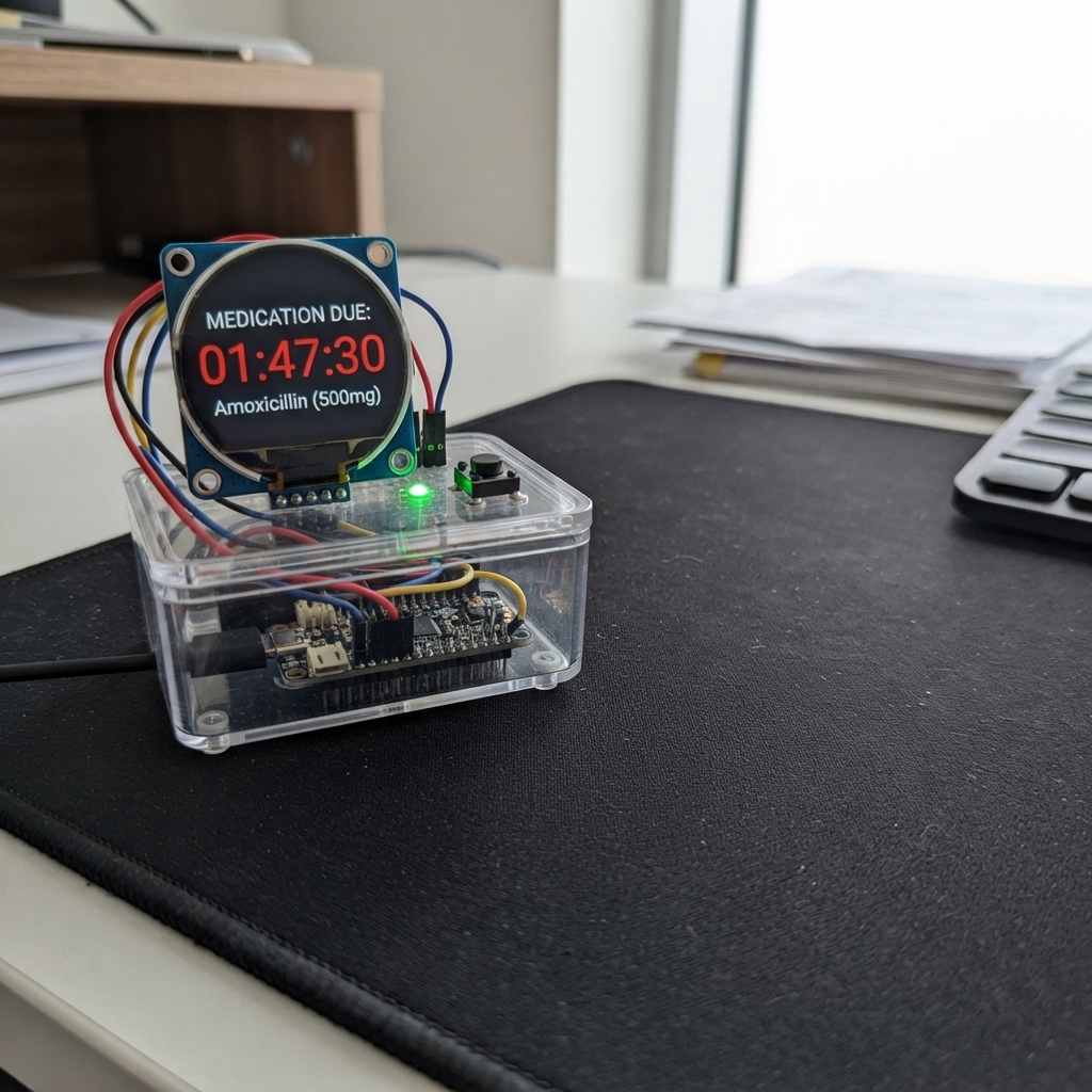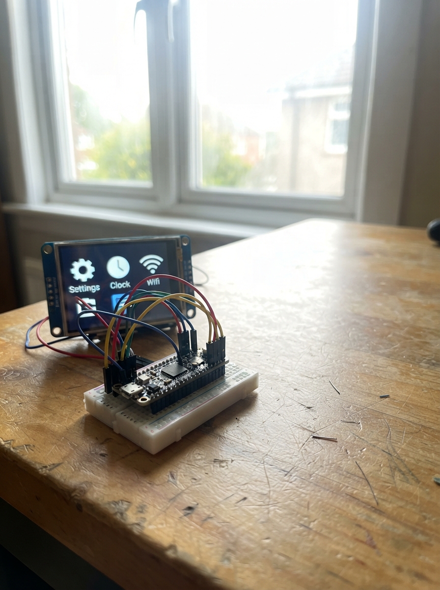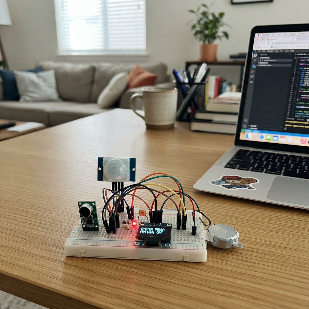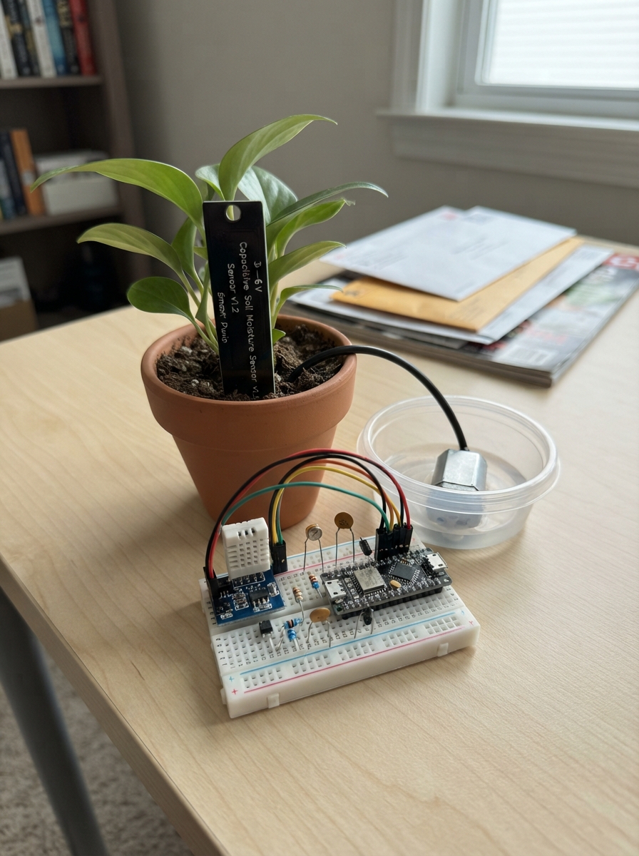
This smart plant care system automatically waters up to three potted plants based on soil moisture, temperature, and light conditions. Built around an ESP32 microcontroller, it combines capacitive soil moisture sensors, a DHT22 temperature/humidity sensor, and a photoresistor to monitor growing conditions in real time. The system drives a submersible pump through a MOSFET circuit and displays status on an OLED screen, with a float switch protecting the water reservoir from running dry.
The guide provides a complete wiring diagram, parts list, and step-by-step assembly instructions covering sensor hookup, pump driver construction, and reservoir plumbing. Included firmware handles WiFi connectivity, calibration routines for each soil probe, and configurable watering thresholds per plant. Builders will verify all connections before first run and can adjust moisture targets and pump runtime to suit different plant types.
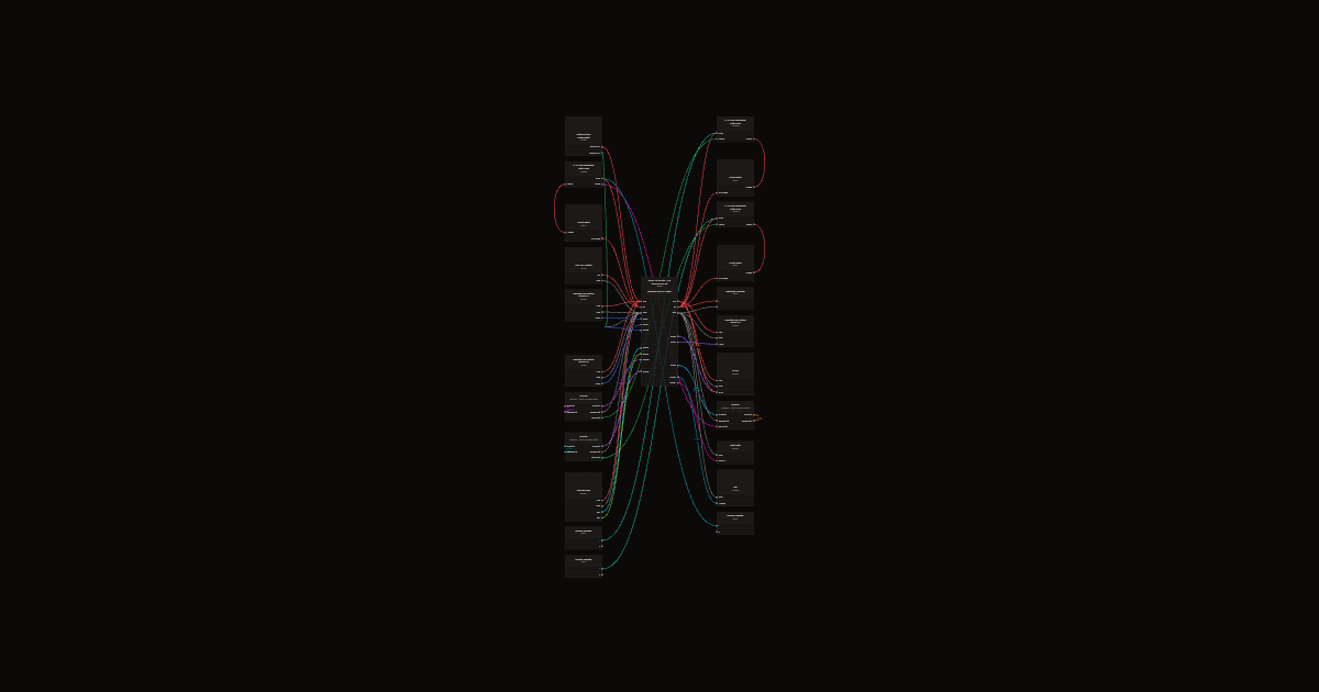
Wiring diagram
Gather all the parts
Assemble it in 17 steps
1. Power off first
Keep USB and the pump adapter unplugged while wiring. Use an enclosed regulated 5 V 4 A adapter for pumps; board gets its own USB power. Connect adapter GND to ESP32 GND but never its positive to board 5V or USB. Use terminal blocks/perfboard for motor current, not loose breadboard contacts.
2. Connect three soil probes
Money Plant AOUT → GPIO1; Snake Plant → GPIO7; Peace Lily → GPIO4 (independent readings). All VCC → 3V3, GND → GND. Keep probe electronics above soil and water.
3. Temperature and light
DHT VCC → 3V3, GND → GND, DATA → GPIO6. Fit 10 kohm from DATA to 3V3. LDR between 3V3 and GPIO5; lightres 10 kohm between GPIO5 and GND.
4. Reservoir safety
Float SIGNAL → GPIO14 and other lead → GND. Orient the float so contacts CLOSE with enough water and OPEN below minimum pump submersion. A disconnected lead must report LOW. This is a level switch, not a continuous volume meter.
5. Screen and status
OLED VCC → 3V3, GND → GND, SDA → GPIO8 (data), SCL → GPIO9 (clock). Check printed labels rather than connector order. GPIO13 → 330 ohm → LED long leg; short leg → GND.
6. Pump driver 1
Use AO3400A on a labeled SOT-23 adapter board. Gate pin 1 → 220 ohm → GPIO10; gate → 10 kohm → GND. Source pin 2 → GND; drain pin 3 → pump negative. Pump positive → pump adapter +5 V. 1N4007 banded cathode → pump positive, unbanded anode → drain. Fit 100 nF across pump terminals. Never connect the pump to a GPIO. Select pump with startup/stall current at most 1 A; verify current briefly with suitable current-limited supply, not by holding a stalled pump.
7. Pump driver 2
Use AO3400A on a labeled SOT-23 adapter board. Gate pin 1 → 220 ohm → GPIO11; gate → 10 kohm → GND. Source pin 2 → GND; drain pin 3 → pump negative. Pump positive → pump adapter +5 V. 1N4007 banded cathode → pump positive, unbanded anode → drain. Fit 100 nF across pump terminals. Never connect the pump to a GPIO. Select pump with startup/stall current at most 1 A; verify current briefly with suitable current-limited supply, not by holding a stalled pump.
8. Pump driver 3
Use AO3400A on a labeled SOT-23 adapter board. Gate pin 1 → 220 ohm → GPIO12; gate → 10 kohm → GND. Source pin 2 → GND; drain pin 3 → pump negative. Pump positive → pump adapter +5 V. 1N4007 banded cathode → pump positive, unbanded anode → drain. Fit 100 nF across pump terminals. Never connect the pump to a GPIO. Select pump with startup/stall current at most 1 A; verify current briefly with suitable current-limited supply, not by holding a stalled pump.
9. Finish power and tubing
Bulk capacitor + → pump +5 V, − stripe → GND. Route motor returns directly to adapter GND; join logic ground at that point. Keep all electronics dry. Submerge only pumps. Put reservoir below pot outlets to prevent siphoning and secure each tube to its own pot.
10. Verify before watering
First test with pump supply unplugged. Verify each sensor and the empty/full float states. Measure each probe in dry soil and saturated drained soil for dashboard calibration. Catch pump output in a measuring cup: the 3 second pulse may deliver substantial water; reduce maxRun in firmware if needed. Supervise first cycles. Reboot disarms automation; calibration persists.
11. Simulation substitutes and prototype limits
# PlantCare AI – Smart Indoor Plant Monitoring and Automated Care System This prototype uses deterministic plant-specific thresholds, not a trained AI model. ## Estimated India budget (not a live quotation) ESP32-S3 board ₹650–950; three capacitive probes ₹300–450; DHT22 ₹180–280; LDR + float ₹100–180; three 3–6 V pumps ₹450–600; three AO3400A on labeled adapter boards + three diodes ₹120–240; OLED ₹150–250; resistors, LED and capacitors ₹80–150; enclosed 5 V 4 A pump supply ₹250–400; perfboard/terminals/wires/tubing ₹200–350. Total about ₹2,580–3,950. Use USB cable/power you already have for the controller. Shipping and tools extra. ## Quantities 3 soil probes; 1 DHT22; 1 LDR; 1 float switch; 3 pumps; 3 AO3400A; 3 1N4007; 1 OLED; 1 green LED; 3 × 220 ohm, 3 × 10 kohm, 2 × 10 kohm, 1 × 330 ohm resistors (9 total); 3 × 100 nF ceramic; 1 × 1000 uF / 10 V electrolytic; 1 enclosed 5 V 4 A pump adapter. ## Simulation limitations and substitutes The electrical checker passed; firmware compiled. No transient motor simulation, water-flow simulation or physical device test has been performed. The catalog has an OLED simulator but not complete models for all selected components. Substitutes below are for a separate simulation/test circuit, NOT additions to the physical bill of materials or delivered wiring: - Replace each soil probe with a catalog potentiometer-10k: VCC to 3V3, GND to GND, WIPER to GPIO1/7/4. Turn it to produce dry/wet raw values. - Replace the LDR divider with another such potentiometer, WIPER to GPIO5. - Replace float with a switch between GPIO14 and GND: closed is water OK; open is low water or a broken wire. A direct virtual switch also suffices. - Replace each pump load with an LED and its own 1 kohm series resistor between pump +5 V and MOSFET drain; observe independent outputs. This tests switching logic only, not inductive spikes, current, flow or MOSFET heat. - If DHT22 is unavailable in the simulator, mock temperature/humidity in a simulation-only copy of firmware; NaN readings in the real firmware indicate a missing/faulty DHT and disarm all pumps. - Model AO3400A as an ideal voltage-controlled low-side switch and 1N4007 as a standard diode if specific simulator models are absent. Real electrical compatibility must still be verified on hardware. No simulator runner is exposed here, so these are a test plan, not claimed results. ## Bench tests 1. With pump power disconnected, boot: all gates LOW, automation OFF. 2. Check raw soil readings, independently calibrate all probes and set their thresholds via dashboard. Login admin / PlantCare123; complete the safety checkbox before arming. 3. Empty float must show LOW; full must show OK after 2 seconds. 4. Arm; first pulse is delayed 30 minutes from boot for safety. Dry one probe: only that plant runs, at most 3 seconds. At most one pump runs at a time. 5. Open float during a pulse: output stops on the next safety-task check (normally within 5 ms). 6. Each plant has a 30 minute cooldown and at most 12 doses per boot. 7. Disconnect probe: rail-level invalid reading disarms all pumps. Floating analog inputs can appear plausible; software cannot detect every probe fault. 8. Restart: new-format calibration retained, automation disarmed. Dose counters reset. Do not use rebooting to bypass the dose cap; this is a supervised prototype. 9. Catch output to measure real volume. Shorten maxRun if 3 seconds is excessive. ## Catalog warnings The 1N4007 catalog voltage labels describe a regulator application, not this flyback use. Here its cathode is at +5 V and anode at the switched drain: reverse biased while pump runs, conducting its turn-off current. Use banded end toward +5 V. Pump supply is a separate named 5 V rail; never connect its positive to controller USB/5V. Verify polarity and actual supply voltage.
12. Final compatibility checks
Existing GPIO wiring is retained: ADC1 GPIO1/7/4 for soil and GPIO5 for light; GPIO6 DHT, GPIO14 float, GPIO8/9 I2C, GPIO10/11/12 gates, GPIO13 LED. No GPIO conflicts. Read actual connector labels; clone soil probes and OLED headers can differ. Verify every analog signal stays between 0 and 3.3 V before connecting. LDR open circuit can look like darkness and is not reliably diagnosable. Soil disconnection can float to a plausible reading. DHT errors or any detected soil fault disarm all pumps. The safety task stops a pulse at a conservative 2980 ms nominal with scheduling latency; this is not a certified hardware timer or independent safety cutout. STOP needs a working phone/network. Float stuck closed, shorted MOSFET, siphoning, and flow are not detectable with these parts. For unattended use an independent hardware cutoff and flow sensing are needed; keep this prototype supervised. Dashboard HTTP is not encrypted; WPA2 protects the local Wi-Fi link. Change password in firmware before use. Calibration and thresholds persist, but boot always disarms; cooldown/dose counters are not persistent. Breadboard only for low-current signals; secure motor wiring. At most one pump runs at a time. OLED failure is reported by missing display, not used as a watering sensor lockout.
13. Engineering audit and dry bench test
No GPIO changes. Real AO3400A SOT-23 pin 1 gate, pin 2 source, pin 3 drain; verify adapter mapping, never infer from simulator graphics. Manufacturer specifies maximum RDS(on) 48 milliohm at VGS 2.5 V; headline 5.7 A rating does not apply to arbitrary breadboard construction. Retained 220 ohm series gates, 10 kohm gate-source pulldowns and one 1N4007 per pump for non-PWM switching. Verify clone probes and OLED header labels and measure analog outputs with probes powered at 3.3 V, disconnected from ESP32 ADC. Expected signals must remain between 0 and 3.3 V. Measure pump starting current before acceptance; 4 A supply adequacy is conditional on combined startup current staying at or below 3 A, with each pump at or below 1 A. Keep both positive rails separate, common ground in a star at supply negative. Watchdog now monitors loop and safety tasks with 2 second panic timeout; safety task also checks 1 second loop heartbeat and 6 second sensor freshness. All cross-task status reads use a locked snapshot; active index is never read twice without locking. Float level is checked again at arming and starting. Calibration now saved as one validated NVS blob per plant; old calibration is intentionally invalidated. Recalibrate after deploying this update. With pump power unplugged and pumps disconnected, measure all gate-source voltages LOW on boot/reset and when disarmed. Verify float open inhibits arming, closed needs two seconds. Save calibration, arm explicitly and wait initial 30 minutes. Simulate dry conditions using actual dry probes: meter each gate, only one must rise and return LOW in under approximately 3 seconds. Test STOP and float opening during this gate-only pulse. Repeat for all plants; verify no repeat within 30 minutes. Disconnect DHT: all outputs must go LOW. Soil unplugging is NOT a reliable fault test: floating ADC can look valid. Watchdog and task timing still need physical fault-injection validation. No physical device or water-flow simulation was run. Existing parts cannot guarantee shutdown after MCU failure, stuck-high GPIO or shorted MOSFET. Independent external power cutoff is required for unattended operation; it is not fitted in this preserved prototype. Do not run pumps dry.
14. Latest timing audit corrections
GPIOs and wiring unchanged. Safety task now samples millis and float only after acquiring the shared lock, avoiding false stale-heartbeat or sensor-timeout trips caused by unsigned subtraction from an older timestamp. Main-task watchdog registration occurs after slow setup operations; pumps remain disarmed during setup. Failed arming commands immediately clear all gate outputs. Calibration blob fields now have explicit upper and lower bounds before subtraction. All changes compiled but timing and watchdog shutdown require gate-only physical testing with pump power disconnected. Detected sensor faults are sampled every 2.5 seconds, not instantaneously; plausible stuck readings and float shorts remain undetectable. Separate software task is not external hardware protection. Never leave this prototype unattended.
15. GPIO migration and final validation
Snake probe is now GPIO7 (ADC1_CH6), previously GPIO2 in the saved project, not GPIO3. Move float SIGNAL from GPIO7 to GPIO14 to avoid conflict. All other GPIOs unchanged. Defaults reset once to 35/20/45 percent while preserving valid calibration; later dashboard threshold edits persist. Pump timing and sampling use millis; short RTOS sleeps only let other tasks run, and fault-only waits never run a pump. Verify float-open disables every gate, startup is disarmed, gate pulses are below 3 seconds, and each plant has a 30-minute cooldown. No physical testing or motor/water simulation is established. Software safety is not an external hardware cutoff; supervise use.
16. Corrected breadboard driver verification
Preserve every current GPIO. Each 220 ohm series gate resistor stays installed. Replace pull1, pull2 and pull3 with 10 kohm; connect each between its own gate and source. Sources and pump adapter negative join ESP32 GND. Drains connect only to their respective pump negatives. Each diode anode joins drain, banded cathode joins separate pump +5 V. Use regulated 5 V 4 A pump supply for a measured combined startup sum no greater than 3 A, with suitably rated cable and secure distribution; higher actual current requires reassessment. Never connect pump positive to ESP32 positive rails or GPIO. AO3400A SOT-23 top-view pins are 1 gate, 2 source, 3 drain; verify the physical adapter mapping by continuity before power, not simulator artwork. All software remains unchanged. Catalog AO3400A has no simulator model; complete motor simulation is not supported here. Verify gate-only behavior before connecting pump power; no physical tests performed.
17. Saved connection reinspection
No wires changed: all four capacitors already have both terminals connected. noise1/noise2/noise3 terminal 1 joins its pump positive and terminal 2 its pump negative; bulk positive joins the separate pump5v rail and negative joins GND. supply positive joins pump5v only; supply negative and all MOSFET sources join ESP32 GND. Each channel retains an individual 220 ohm gate resistor, 10 kohm gate-source pulldown, and diode anode to pump negative with cathode to pump5v. This verifies the saved netlist only, not physical breadboard continuity, component polarity, adapter pin order or supply performance. Two stale simulation-plan GPIO labels were corrected to soil GPIO1/7/4 and float GPIO14. Firmware and all circuit GPIOs unchanged. Keep pump power disconnected for initial testing.
Review all connections
1. Connections between "soil1" and "ESP32"
2. Connections between "pump1" and "ESP32"
3. Connections between "q1" and "ESP32"
4. Connections between "gate1" and "ESP32"
5. Connections between "pull1" and "ESP32"
6. Connections between "diode1" and "ESP32"
7. Connections between "noise1" and "ESP32"
8. Connections between "soil2" and "ESP32"
9. Connections between "pump2" and "ESP32"
10. Connections between "q2" and "ESP32"
11. Connections between "gate2" and "ESP32"
12. Connections between "pull2" and "ESP32"
13. Connections between "diode2" and "ESP32"
14. Connections between "noise2" and "ESP32"
15. Connections between "soil3" and "ESP32"
16. Connections between "pump3" and "ESP32"
17. Connections between "q3" and "ESP32"
18. Connections between "gate3" and "ESP32"
19. Connections between "pull3" and "ESP32"
20. Connections between "diode3" and "ESP32"
21. Connections between "noise3" and "ESP32"
22. Connections between "dht" and "ESP32"
23. Connections between "dhtpull" and "ESP32"
24. Connections between "ldr" and "ESP32"
25. Connections between "lightres" and "ESP32"
26. Connections between "level" and "ESP32"
27. Connections between "oled" and "ESP32"
28. Connections between "ledres" and "ESP32"
29. Connections between "status" and "ESP32"
30. Connections between "supply" and "ESP32"
31. Connections between "bulk" and "ESP32"
Deploy the firmware
#include <Arduino.h>
#include <esp_task_wdt.h>
#include <esp_idf_version.h>
#include <Wire.h>
#include <WiFi.h>
#include <WebServer.h>
#include <Preferences.h>
#include <DHT.h>
#include <Adafruit_GFX.h>
#include <Adafruit_SSD1306.h>

const int soilPins[3]={1,7,4}, pumpPins[3]={10,11,12};
const char* names[3]={"Money Plant","Snake Plant","Peace Lily"};
const char* password="PlantCare123"; // Change before deployment (8+ characters).
const uint32_t cooldown=1800000, maxRun=3000;

DHT dht(6,DHT22);
Adafruit_SSD1306 oled(128,64,&Wire,-1);
WebServer server(80);
Preferences prefs;

portMUX_TYPE mux=portMUX_INITIALIZER_UNLOCKED;
volatile bool enabled=false, tank=false, fault=true;
volatile int active=-1;
volatile uint32_t startAt=0, stopped[3]={}, sampledAt=0;
volatile uint32_t loopBeat=0;

int raw[3]={}, moisture[3]={}, dry[3]={3000,3000,3000};
int wet[3]={1400,1400,1400}, threshold[3]={35,20,45}, doses[3]={};
bool calibrated[3]={}, valid[3]={}, screen=false, checked=false;
int light=0;
float temp=NAN, humidity=NAN;
String oldFrame;

struct State {
  bool armed, water, error;
  int pump;
};

State snapshot(){
  portENTER_CRITICAL(&mux);
  State s={enabled,tank,fault,active};
  portEXIT_CRITICAL(&mux);
  return s;
}

struct Calibration {
  uint32_t magic;
  int d,w,t;
};

bool goodCal(const Calibration &c){
  return c.magic==0x50434132 &&
         c.w>=100 && c.w<=3900 && c.d>=100 && c.d<=3900 &&
         c.d-c.w>=300 && c.t>=5 && c.t<=80;
}

void disarm();

void fatal(){
  disarm();
  for(;;) delay(100);
}

// Caller must hold mux.
void stopLocked(){
  for(int i=0;i<3;i++) digitalWrite(pumpPins[i],LOW);
  if(active>=0) stopped[active]=millis();
  active=-1;
}

void disarm(){
  portENTER_CRITICAL(&mux);
  enabled=false;
  stopLocked();
  portEXIT_CRITICAL(&mux);
}

void safetyTask(void*){
  if(esp_task_wdt_add(nullptr)!=ESP_OK) fatal();
  uint32_t openAt=millis();

  for(;;){
    portENTER_CRITICAL(&mux);
    // Sample time AFTER acquiring the lock: timestamps may have advanced
    // while this task was waiting. Older now values cause unsigned underflow.
    uint32_t now=millis();
    bool closed=digitalRead(14)==LOW;

    if(!closed){
      openAt=now;
      tank=false;
      enabled=false;
      stopLocked();
    }else{
      tank=(uint32_t)(now-openAt)>=2000;
    }

    if(fault ||
       (uint32_t)(now-sampledAt)>6000 ||
       (uint32_t)(now-loopBeat)>1000){
      enabled=false;
      stopLocked();
    }

    // Conservative nominal cutoff leaves some scheduling margin.
    if(active>=0 &&
       (!enabled || !tank ||
        (uint32_t)(now-startAt)>=maxRun-20)){
      stopLocked();
    }

    portEXIT_CRITICAL(&mux);

    esp_task_wdt_reset();
    vTaskDelay(pdMS_TO_TICKS(5));
  }
}

bool auth(){
  if(server.authenticate("admin",password)) return true;
  server.requestAuthentication();
  return false;
}

bool number(const char* key,int &value){
  String s=server.arg(key);
  if(!s.length() || s.length()>4) return false;
  for(unsigned i=0;i<s.length();i++){
    if(s[i]<'0'||s[i]>'9') return false;
  }
  value=s.toInt();
  return true;
}

String readings(){
  State st=snapshot();
  String s="PlantCare AI\n";

  for(int i=0;i<3;i++){
    s+=String(names[i])+": "+moisture[i]+"% raw="+raw[i]+
       " threshold="+threshold[i]+"% "+
       (calibrated[i]?"calibrated":"CALIBRATE")+" "+
       (valid[i]?"OK":"FAULT")+" doses="+doses[i]+"\n";
  }

  s+="Temperature: "+String(temp,1)+" C Humidity: "+
     String(humidity,0)+"%\nLight (relative): "+light+
     "%\nReservoir: "+
     String(st.water?"OK":"LOW / disconnected")+
     "\nAutomation: "+String(st.armed?"ARMED":"OFF")+
     "\nPump: "+
     String(st.pump<0?"OFF":names[st.pump])+
     "\nSafety: "+
     String(st.error?"SENSOR FAULT":"OK")+"\n";

  return s;
}

const char page[] PROGMEM=R"HTML(
<!doctype html>
<meta name="viewport" content="width=device-width,initial-scale=1">
<title>PlantCare AI</title>
<h2>PlantCare AI</h2>
<pre id="r">Loading</pre>

<label>
<input type="checkbox" id="safe">
I tested empty/full reservoir, sensor readings, pump mapping,
and measured safe dose volume
</label>

<p>
<button onclick="arm(1)">Enable automatic watering</button>
<button onclick="arm(0)">EMERGENCY STOP / Disable</button>
</p>

<p>
Always boots disarmed. Initial delay and cooldown: 30 minutes.
Maximum pulse: 3 seconds. Maximum 12 doses per plant per boot.
Faults require re-arming.
</p>

<h3>Calibration and threshold</h3>
<p>
Record raw readings in dry soil and saturated, drained soil separately
for each plant. Percent is relative, not scientific water content.
Saving stops watering.
</p>

<form method="POST" action="/cal">
<select name="i">
<option value="0">Money Plant</option>
<option value="1">Snake Plant</option>
<option value="2">Peace Lily</option>
</select>
<input name="d" type="number" min="100" max="3900"
       placeholder="Dry raw" required>
<input name="w" type="number" min="100" max="3900"
       placeholder="Wet raw" required>
<input name="t" type="number" min="5" max="80"
       placeholder="Threshold %" required>
<button>Save</button>
</form>

<script>
async function update(){
  document.getElementById('r').textContent=
    await(await fetch('/read')).text()
}
async function arm(x){
  alert(await(await fetch('/arm',{
    method:'POST',
    headers:{'Content-Type':'application/x-www-form-urlencoded'},
    body:'on='+x+'&check='+
      (document.getElementById('safe').checked?1:0)
  })).text());
  update()
}
setInterval(update,1000);
update()
</script>
)HTML";

void setup(){
  for(int i=0;i<3;i++){
    digitalWrite(pumpPins[i],LOW);
    pinMode(pumpPins[i],OUTPUT);
    stopped[i]=millis();
  }

  pinMode(14,INPUT_PULLUP);
  pinMode(13,OUTPUT);
  Serial.begin(115200);

  analogReadResolution(12);
  analogSetAttenuation(ADC_11db);
  sampledAt=loopBeat=millis();

#if ESP_IDF_VERSION_MAJOR >= 5
  esp_task_wdt_config_t wc={};
  wc.timeout_ms=2000;
  wc.trigger_panic=true;
  esp_err_t wr=esp_task_wdt_init(&wc);
  if(wr==ESP_ERR_INVALID_STATE){
    wr=esp_task_wdt_reconfigure(&wc);
  }
#else
  esp_err_t wr=esp_task_wdt_init(2,true);
#endif

  if(wr!=ESP_OK) fatal();
  // Register the main task only after potentially slow startup operations.
  // Pumps remain disarmed throughout setup; safety task is monitored now.

  if(xTaskCreate(safetyTask,"pumpSafety",2048,nullptr,3,nullptr)
     !=pdPASS){
    for(;;){
      disarm();
      delay(100);
    }
  }

  dht.begin();
  Wire.begin(8,9);
  Wire.setTimeOut(50);
  screen=oled.begin(SSD1306_SWITCHCAPVCC,0x3C);

  bool storage=prefs.begin("plantcare",false);

  for(int i=0;i<3;i++){
    Calibration c={};
    String k="v"+String(i);

    if(storage &&
       prefs.getBytes(k.c_str(),&c,sizeof(c))==sizeof(c) &&
       goodCal(c)){
      dry[i]=c.d;
      wet[i]=c.w;
      threshold[i]=prefs.getBool("thresholdsV2",false)?c.t:threshold[i];
      calibrated[i]=true;
    }
    // Legacy multi-key calibration deliberately requires re-calibration.
  }

  if(storage && !prefs.getBool("thresholdsV2",false)){
    bool saved=true;
    for(int i=0;i<3;i++){
      if(!calibrated[i]) continue;
      Calibration c={0x50434132,dry[i],wet[i],threshold[i]};
      String k="v"+String(i);
      saved=(prefs.putBytes(k.c_str(),&c,sizeof(c))==sizeof(c))&&saved;
    }
    if(saved) prefs.putBool("thresholdsV2",true);
    else for(int i=0;i<3;i++) calibrated[i]=false;
  }

  WiFi.mode(WIFI_AP);
  WiFi.softAP("PlantCare-AI",password);

  server.on("/",HTTP_GET,[]{
    if(auth()) server.send_P(200,"text/html",page);
  });

  server.on("/read",HTTP_GET,[]{
    if(auth()) server.send(200,"text/plain",readings());
  });

  server.on("/arm",HTTP_POST,[]{
    if(!auth()) return;

    if(server.arg("on")=="0"){
      disarm();
      server.send(200,"text/plain",
                  "All pumps OFF; automation disabled");
      return;
    }

    if(server.arg("on")!="1"){
      disarm();
      server.send(400,"text/plain","Invalid command");
      return;
    }

    checked=server.arg("check")=="1";
    bool ok=checked;

    for(int i=0;i<3;i++){
      ok=ok&&calibrated[i]&&valid[i];
    }

    portENTER_CRITICAL(&mux);
    ok=ok&&tank&&digitalRead(14)==LOW&&!fault&&
       (uint32_t)(millis()-sampledAt)<6000;
    enabled=ok;
    if(!ok) stopLocked();
    portEXIT_CRITICAL(&mux);

    server.send(ok?200:409,"text/plain",
      ok?"Armed. 30-minute initial delay/cooldowns apply.":
         "Blocked: complete calibration, safety checklist, "
         "and check all sensors/tank.");
  });

  server.on("/cal",HTTP_POST,[]{
    if(!auth()) return;

    disarm();
    checked=false;
    int i,d,w,t;

    if(!number("i",i)||!number("d",d)||!number("w",w)||
       !number("t",t)||i>2||w<100||d>3900||d-w<300||
       t<5||t>80){
      server.send(400,"text/plain",
        "Require valid plant, dry > wet by 300+, "
        "raw 100..3900, threshold 5..80.");
      return;
    }

    String k="v"+String(i);
    Calibration c={0x50434132,d,w,t};
    bool ok=prefs.putBytes(k.c_str(),&c,sizeof(c))==sizeof(c);

    dry[i]=d;
    wet[i]=w;
    threshold[i]=t;
    calibrated[i]=ok;

    server.send(ok?200:500,"text/html",
      ok?"Saved. <a href='/'>Return</a>":
         "Storage error; watering blocked.");
  });

  server.begin();
  portENTER_CRITICAL(&mux);
  loopBeat=millis();
  portEXIT_CRITICAL(&mux);
  if(esp_task_wdt_add(nullptr)!=ESP_OK) fatal();

  Serial.println(
    "Wi-Fi PlantCare-AI / PlantCare123; "
    "http://192.168.4.1 ; login admin / same password");
}

void loop(){
  portENTER_CRITICAL(&mux);
  loopBeat=millis();
  portEXIT_CRITICAL(&mux);
  esp_task_wdt_reset();

  static uint32_t lastSample=0;
  uint32_t now=millis();

  if((uint32_t)(now-lastSample)>=2500){
    lastSample=now;
    bool bad=false;

    for(int i=0;i<3;i++){
      long sum=0;
      for(int n=0;n<16;n++){
        sum+=analogRead(soilPins[i]);
      }
      raw[i]=sum/16;

      valid[i]=raw[i]>80&&raw[i]<4000 &&
        (!calibrated[i] ||
         (raw[i]>=wet[i]-250 && raw[i]<=dry[i]+250));

      bad=bad||!valid[i];

      moisture[i]=dry[i]>wet[i]?
        constrain((dry[i]-raw[i])*100/
                  (dry[i]-wet[i]),0,100):0;
    }

    int l=analogRead(5);
    light=l*100/4095;
    temp=dht.readTemperature();
    humidity=dht.readHumidity();

    bad=bad||isnan(temp)||isnan(humidity)||
        temp< -40||temp>80||humidity<0||humidity>100;

    portENTER_CRITICAL(&mux);
    fault=bad;
    sampledAt=millis();

    if(bad){
      enabled=false;
      stopLocked();
    }

    if(enabled&&tank&&digitalRead(14)==LOW&&
       active<0&&!fault){
      for(int i=0;i<3;i++){
        if(calibrated[i]&&valid[i]&&
           moisture[i]<threshold[i]&&
           (uint32_t)(millis()-stopped[i])>=cooldown&&
           doses[i]<12){
          active=i;
          startAt=millis();
          doses[i]++;
          digitalWrite(pumpPins[i],HIGH);
          break;
        }
      }
    }
    portEXIT_CRITICAL(&mux);
  }

  server.handleClient();

  State st=snapshot();
  String frame="PlantCare AI\n";

  for(int i=0;i<3;i++){
    frame+=String(i+1)+": "+moisture[i]+"% "+
           (valid[i]?"":"ERR")+"\n";
  }

  frame+=String(temp,1)+"C "+String(humidity,0)+"% L"+
         light+"\n"+(st.water?"Tank OK ":"Tank LOW ")+
         (st.armed?"ARMED":"OFF")+"\nPump "+
         String(st.pump+1)+(st.error?" FAULT":"")+
         "\n192.168.4.1";

  if(screen&&frame!=oldFrame){
    oldFrame=frame;
    oled.clearDisplay();
    oled.setTextSize(1);
    oled.setTextColor(SSD1306_WHITE);
    oled.setCursor(0,0);
    oled.print(frame);
    oled.display();
  }

  digitalWrite(13,(!st.water||st.error)?
    ((millis()/300)%2):(st.pump>=0?HIGH:LOW));

  // Scheduler sleep only; watering and sampling deadlines use millis().
  vTaskDelay(1);
}
Remix this project
Make it yours in one click
Open a full copy of this project in your own Schematik workspace, diagram, code, parts, and assembly steps included. Swap the sensor, add features, or redesign the whole thing with AI. The author's original stays untouched.