Community project
Define Ads1220_sck_pin 2 Define Ads1220_mosi_pin
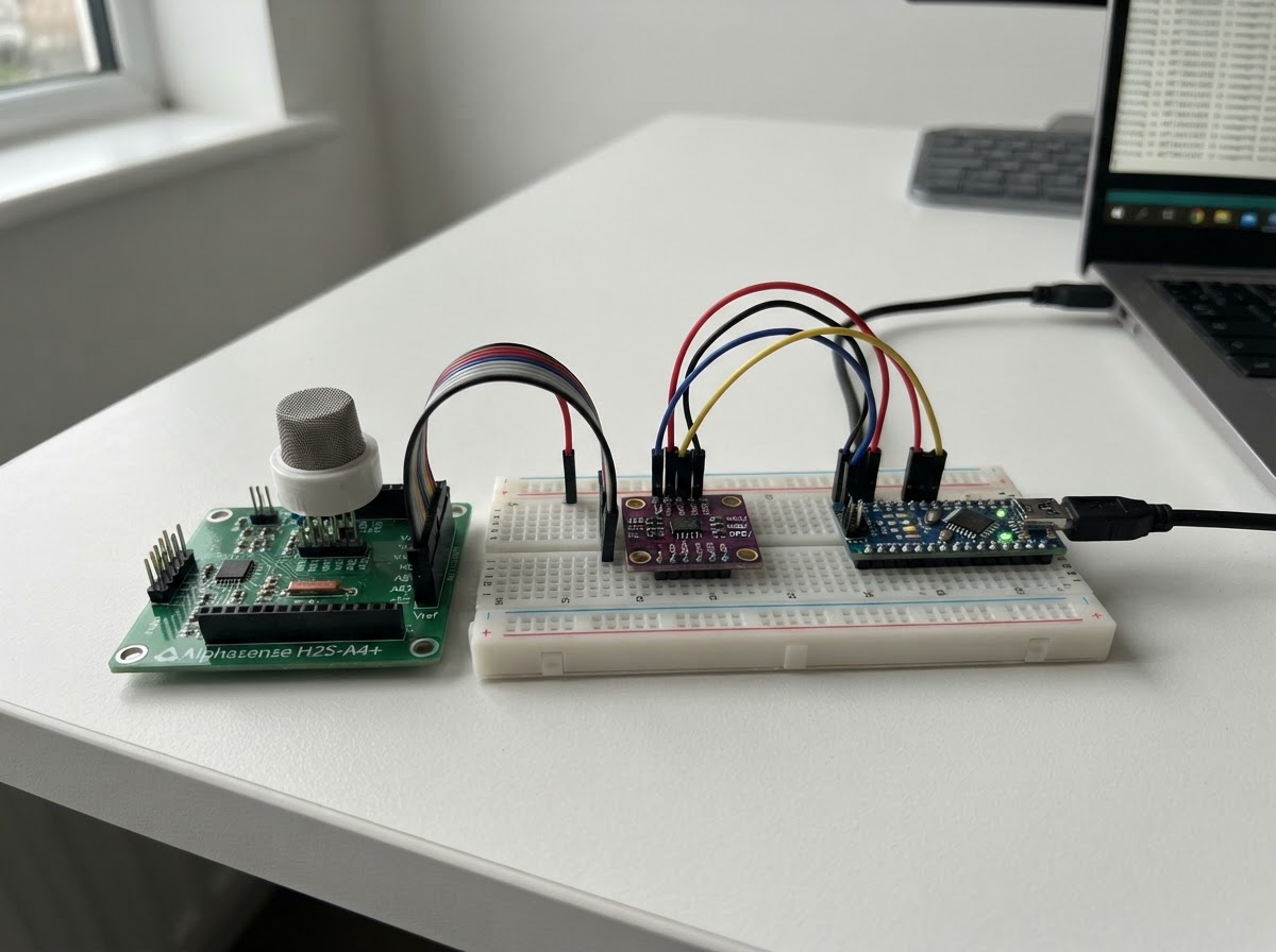
This project measures hydrogen sulfide (H2S) gas concentration using an Alphasense H2S-A4+ electrochemical sensor connected to a Raspberry Pi Pico W. The sensor cartridge installs in the SN1 socket of an Alphasense A4×2 analog front end (AFE), which conditions the sensor signal and provides temperature compensation via an integrated Pt1000 thermistor. The ADS1220 24-bit ADC bridges the AFE outputs to the Pico W over SPI, enabling high-resolution gas measurements.
This guide provides the complete wiring diagram, parts list, and firmware to get started. Assembly takes about 30 minutes and requires careful attention to the AFE header pinout and SPI connections. The firmware reads both the H2S sensor output and temperature reference, with raw ADC values displayed for verification and calibration.
Wiring diagram

Gather all the parts
Assemble it in 8 steps
1. Keep the AFE unpowered while wiring
Disconnect the Pico W USB cable before inserting the H2S sensor or making any connections. Handle the electrochemical sensor by its body; do not touch the gold contact pins.
- Use a grounded work surface if available.
- Do not apply power until all ground connections are complete.
- Reversing the supply pins can damage the AFE.
2. Install the H2S sensor in the SN1 socket
On the rear of the A4×2 AFE Iss.2, install the H2S-A4+ cartridge in the socket marked SN1 (the right-hand socket in the supplied rear-board image). Align the sensor’s key/index marking with the socket orientation before pressing it straight down. Leave the SN2 socket empty.
- The sensor electrodes are connected internally by this socket; do not wire WE, AE, RE, or CE to the ADS1220.
- Do not force the sensor: incorrect orientation can bend contacts or damage the cartridge.
3. Identify the rear 2×5 AFE header
View the rear of the AFE with the printed text upright and the 2×5 header at the bottom. The upper row, from left to right, is +6V, NC, SN2, SN1, PT. The lower row is GND for each corresponding upper-row position. Use the supplied 10-way ribbon cable only after confirming its pin-1 orientation.
- For this build, only +6V, its GND, SN1, its GND, PT, and its GND are used.
- Leave both NC pins and both SN2 pins unconnected.
- The upper-left +6V pin is the only supply input; it is not a signal pin.
4. Power and ground the AFE
Connect AFE +6V (upper-left header pin) to Pico W VBUS/5V. Connect the lower-left GND pin to the common ground rail. Also connect the lower-row GND pins underneath SN1 and PT to that same common ground rail.
- USB-powered Pico W VBUS provides approximately 5 V, within the AFE 3.4–6.4 V input range.
- All grounds—Pico, ADS1220 AGND/DGND, and AFE ground returns—must join together.
- Never connect the AFE +6V pin to Pico 3V3.
5. Connect AFE analogue outputs to ADS1220
Connect the upper-row SN1 pin (fourth pair) to ADS1220 AIN0. Connect the upper-row PT pin (fifth pair) to ADS1220 AIN2. Keep both leads short and route them away from the Pico USB cable and SPI wires. AIN1 remains open.
- The lower-row pins below SN1 and PT are their ground returns; both connect to ADS1220 AGND/common ground.
- SN1 is a conditioned AFE output, not a direct electrode wire.
- Do not connect NC or SN2 to the ADC in this one-sensor build.
6. Power the ADS1220 at 3.3 V
Connect ADS1220 AVDD and DVDD to Pico W 3V3. Connect ADS1220 AGND and DGND to the shared ground rail used by the AFE.
- Using 3.3 V for both ADS1220 supplies makes its SPI logic safe for Pico W GPIO.
- Place the ADS1220 close to the AFE to reduce analogue pickup.
- Do not feed 5 V into ADS1220 DVDD when it is connected to Pico W SPI pins.
7. Wire SPI between the ADS1220 and Pico W
Connect ADS1220 DOUT to Pico GP0, CS to GP1, SCLK to GP2, DIN to GP3, and DRDY to GP6. Verify each connection before applying USB power.
- DOUT is ADS1220-to-Pico data (MISO); DIN is Pico-to-ADS1220 data (MOSI).
- Keep the SPI leads short and separate from SN1/PT analogue leads.
- Do not use other GPIO numbers: the supplied firmware is written for these exact wired pins.
8. Apply power and inspect raw readings
Connect the Pico W to USB. Use Schematik’s Deploy button to flash the project. The firmware prints CSV values in the form SN1_mV,PT_mV every five seconds; first confirm that values are stable before deriving concentration from calibration data.
- Allow the electrochemical sensor to stabilise according to its datasheet before interpreting values.
- Record baseline readings in clean air for later calibration work.
- This firmware intentionally reports raw AFE outputs only. Do not use it as a safety alarm or concentration meter until a sensor-specific, documented calibration method is added.
Review all connections
1. Connections between "ads1220" and "Raspberry Pi Pico"
2. Connections between "h2s_sensor" and "Raspberry Pi Pico"
3. Connections between "afe_board" and "Raspberry Pi Pico"
Deploy the firmware
/*
 * Alphasense H2S-A4+ in SN1 socket of A4x2 AFE Iss.2
 * Raspberry Pi Pico W + ADS1220
 *
 * A4x2 rear 2x5 header, viewed with rear-board text upright and header below:
 *   Upper row, left to right: +6V, NC, SN2, SN1, PT
 *   Lower row, left to right: GND, GND, GND, GND, GND
 *
 * This single-sensor build uses only SN1 and PT:
 *   AFE SN1 (upper pin, fourth pair) -> ADS1220 AIN0
 *   AFE PT  (upper pin, fifth pair)  -> ADS1220 AIN2
 *   Corresponding lower pins          -> common AGND/GND
 *
 * The individual WE/AE/RE/CE sensor electrodes are internal connections
 * between the H2S-A4+ cartridge and the AFE's SN1 socket. They must not be
 * connected to the ADS1220 header wiring.
 *
 * SPI0 on Pico W: MISO=GP0, CS=GP1, SCK=GP2, MOSI=GP3, DRDY=GP6.
 */

#include <Arduino.h>
#include <SPI.h>
#include "Protocentral_ADS1220.h"

#define ADS1220_SCK_PIN   2
#define ADS1220_MOSI_PIN  3
#define ADS1220_MISO_PIN  0
#define ADS1220_CS_PIN    1
#define ADS1220_DRDY_PIN  6


// Forward declarations
float readChannelMv(uint8_t channel);

Protocentral_ADS1220 adc;

float readChannelMv(uint8_t channel) {
  // ADS1220 single-ended mux selections: AIN0/AVSS = 0x08, AIN2/AVSS = 0x0A.
  adc.set_mux(0x08 + (channel & 0x03));
  adc.Start_Conv();

  const uint32_t startMs = millis();
  while (digitalRead(ADS1220_DRDY_PIN) == HIGH) {
    if (millis() - startMs > 500) {
      return NAN;
    }
  }

  const int32_t raw = adc.Read_Data_Samples();
  // Gain 1, internal 2.048 V reference, signed 24-bit conversion result.
  const float lsbMv = (2.0f * 2048.0f) / 16777216.0f;
  return raw * lsbMv;
}

void setup() {
  Serial.begin(115200);
  const uint32_t startMs = millis();
  while (!Serial && millis() - startMs < 3000) { }

  SPI.setRX(ADS1220_MISO_PIN);
  SPI.setSCK(ADS1220_SCK_PIN);
  SPI.setTX(ADS1220_MOSI_PIN);

  pinMode(ADS1220_DRDY_PIN, INPUT_PULLUP);
  adc.begin(ADS1220_CS_PIN, ADS1220_DRDY_PIN);
  adc.set_pga_gain(PGA_GAIN_1);
  adc.set_data_rate(DR_20SPS);
  adc.set_conv_mode_single_shot();
  adc.set_voltage_ref(VREF_INTERNAL);

  Serial.println(F("AFE Iss.2 raw-output monitor"));
  Serial.println(F("CSV: SN1_mV,PT_mV"));
}

void loop() {
  const float sn1Mv = readChannelMv(0);
  const float ptMv = readChannelMv(2);

  if (isnan(sn1Mv) || isnan(ptMv)) {
    Serial.println(F("ERROR,ADS1220 DRDY timeout"));
  } else {
    Serial.print(sn1Mv, 3);
    Serial.print(',');
    Serial.println(ptMv, 3);
  }

  // Electrochemical sensors change slowly; an event is logged every 5 seconds.
  delay(5000);
}
Remix this project
Make it yours in one click
Open a full copy of this project in your own Schematik workspace — diagram, code, parts, and assembly steps included. Swap the sensor, add features, or redesign the whole thing with AI. The author's original stays untouched.
Related projects
Drone Light Safety Controller (copy)
Raspberry Pi Pico · September 26, 2026ianlex.wip
RGB Button Color Controller
Raspberry Pi Pico · September 25, 2026juliaccquintanilha
Zaprojektuj Emulator Rom Dla Zx Spectrum Harlequ
Raspberry Pi Pico · September 25, 2026Piotr Chmielecki