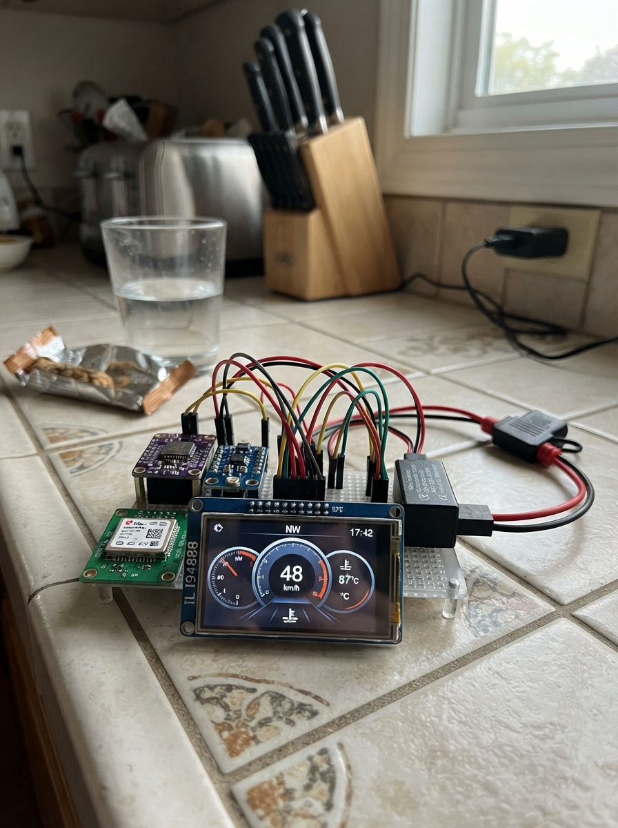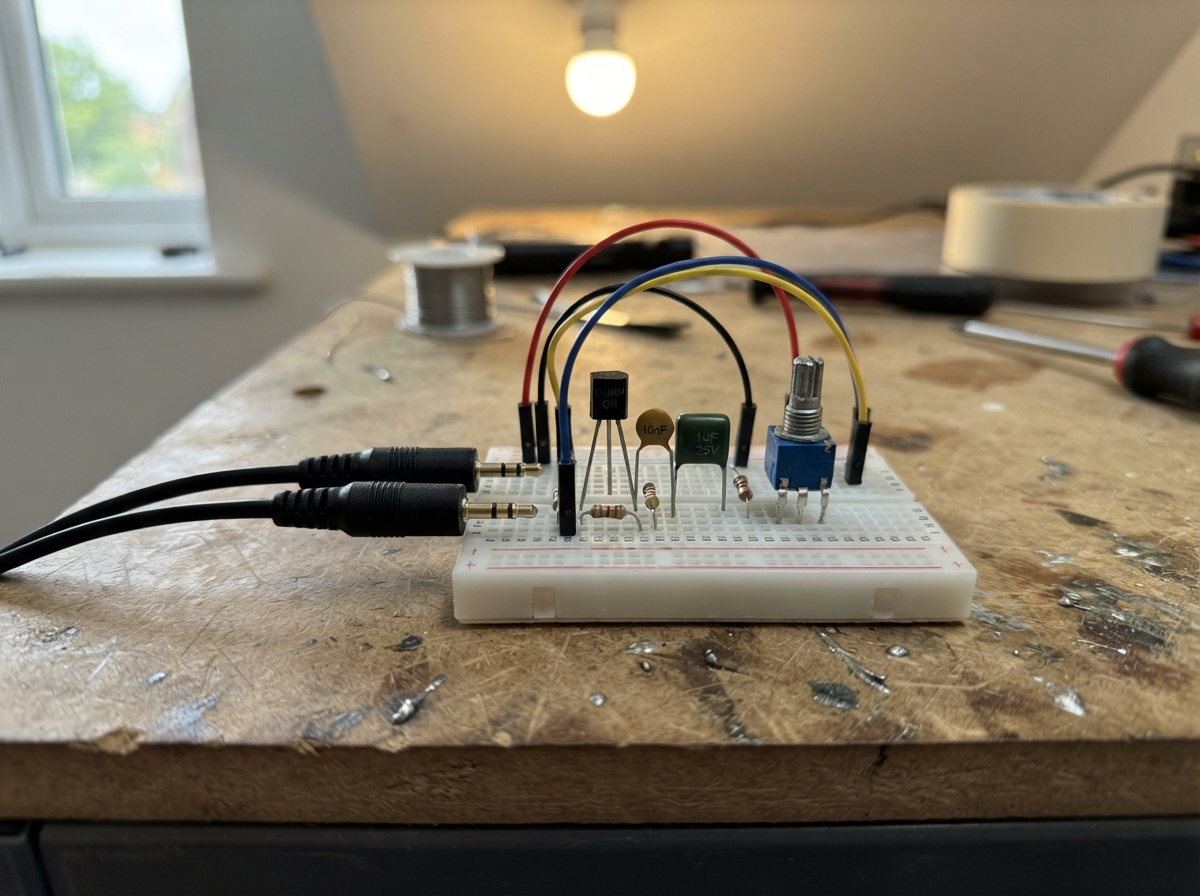
This guide builds a portable AX.25 packet radio terminal node controller (TNC) using a Raspberry Pi Pico, enabling digital communication over VHF/UHF amateur radio networks. The project interfaces a Kenwood radio via a two-plug cable and implements Bell 202 1200-baud modem firmware on the Pico's dual cores, with one core dedicated to real-time audio processing and PTT control.
Readers will receive a complete wiring diagram showing the transmit switch, microphone audio path, and receive level control circuits built from discrete components, a full parts list, the Arduino-compatible firmware implementing HDLC frame encoding and AX.25 packet handling, and step-by-step assembly instructions including pre-radio connection verification and configuration steps.
Wiring diagram
Gather all the parts
Assemble it in 6 steps
1. Identify the radio cable contacts
Use a bare-ended K1 speaker-microphone cable, not a USB programming cable. Use continuity mode with everything unplugged: 3.5mm ring is MIC; 3.5mm sleeve is PTT; 2.5mm tip is SPK; 2.5mm sleeve is GND. Insulate the unused 3.5mm tip and 2.5mm ring separately. Do not trust cable colours.
- This design is for the standard common-ground K1 audio port, not every radio with two sockets. Confirm the contact functions against your radio manual before connecting. Never short the 3.5mm tip to ground.
2. Build the transmit switch
GP14 drives rb (4.7k), then q1 base. q1 emitter goes to GND and collector to radio PTT. Fit rbe (100k) between base and GND to keep the radio unkeyed during startup. Use the onsemi TO-92 drawing: pin 1 E, 2 B, 3 C.
3. Build the microphone audio path
GP15 feeds rf (4.7k). Connect cf (10nF) from its far end to GND, and rt (100k) from that point to rl (1k). Ground the far end of rl. Connect ct (1uF non-polar) from the rt/rl junction to radio MIC. The filter removes the PWM carrier, the divider reduces the audio level, and ct blocks microphone bias.
4. Build the receive level control
Radio SPK feeds cr (1uF non-polar), then rv TOP. Ground rv BOTTOM. Connect rv WIPER through ri (47k) to GP26 (audio input). Connect ru (10k) from 3V3 to GP26 and rd (10k) from GP26 to GND. Connect radio GND to Pico GND. The resistors hold the ADC near 1.65V and reduce speaker level.
- Never connect speaker output directly to GP26. Use only a common-ground handheld speaker output, no more than 10V peak, not a bridge-output amplifier or mobile radio speaker output.
5. Check before connecting the radio
Keep the radio unplugged. Inspect for shorts. Start with rv wiper at its grounded end. With Pico powered by USB, verify GP26 is near 1.65V. Power the radio off before inserting both K1 plugs fully. Power the radio from its own battery, not the Pico; leave its charger disconnected.
- A partly inserted plug can key the radio. Attach an antenna or suitable dummy load before powering the radio. Never transmit without a load.
6. Set up the radio for packet audio
Use analog FM, turn off VOX, scan, battery saver, and audio companding. Use open squelch if possible. Start speaker volume low, then raise it and rv gradually while receiving known 1200-baud packet traffic. This simple software modem needs bench testing and level adjustment. Keep audio and ground leads short and away from the antenna.
- Transmit only on frequencies and with a callsign permitted by your amateur licence. This is not for unlicensed FRS/PMR446 packet operation. The initial microphone level is deliberately low; verify deviation with suitable test equipment before on-air use.
Review all connections
1. Connections between "radio" and "Raspberry Pi Pico"
2. Connections between "q1" and "Raspberry Pi Pico"
3. Connections between "rb" and "Raspberry Pi Pico"
4. Connections between "rbe" and "Raspberry Pi Pico"
5. Connections between "rf" and "Raspberry Pi Pico"
6. Connections between "cf" and "Raspberry Pi Pico"
7. Connections between "rt" and "Raspberry Pi Pico"
8. Connections between "rl" and "Raspberry Pi Pico"
9. Connections between "ct" and "Raspberry Pi Pico"
10. Connections between "cr" and "Raspberry Pi Pico"
11. Connections between "rv" and "Raspberry Pi Pico"
12. Connections between "ri" and "Raspberry Pi Pico"
13. Connections between "ru" and "Raspberry Pi Pico"
14. Connections between "rd" and "Raspberry Pi Pico"
Deploy the firmware
#include <Arduino.h>
#include <math.h>
#include <pico/time.h>
#include <hardware/sync.h>
// Pin table confirmed: GP14 PTT via rb, GP15 PWM via rf, GP26 RX via ri.
// Bell 202, 1200 baud. Core 1 owns all real-time audio and PTT.
constexpr int RX=26, AUDIO=15, PTT=14, FS=26400, SPB=22, MAXFRAME=330;
volatile bool audioReady=false, txReady=false, rxReady=false, busy=false;
uint8_t txBits[6000], rxFrame[MAXFRAME+2];
volatile unsigned txCount=0, rxLength=0;
uint8_t pending[MAXFRAME]; unsigned pendingLen=0;
uint8_t txDelay=30, persistence=63, slotTime=10, txTail=3;
bool fullDuplex=false;
float sinTab[FS/100], cm[22],sm[22],cs[22],ss[22];
uint16_t crcStep(uint16_t c,uint8_t b){c^=b;for(int i=0;i<8;i++)c=(c>>1)^((c&1)?0x8408:0);return c;}
void kissByte(uint8_t b){if(b==0xc0){Serial.write(0xdb);Serial.write(0xdc);}else if(b==0xdb){Serial.write(0xdb);Serial.write(0xdd);}else Serial.write(b);}
// Decode a whole HDLC frame only after a closing flag; strip stuffing then FCS.
uint8_t raw[6000]; unsigned rawN=0; bool inFrame=false; uint8_t flagShift=0;
void receiveBit(bool bit){
 flagShift=(flagShift>>1)|(bit?128:0);
 if(inFrame){if(rawN<sizeof(raw))raw[rawN++]=bit;else{inFrame=false;rawN=0;}}
 if(flagShift!=0x7e)return;
 if(inFrame && rawN>=8){
  unsigned n=rawN-8,len=0,bc=0,ones=0;uint8_t b=0;uint16_t crc=0xffff;bool ok=true;
  uint8_t frame[MAXFRAME+2];
  for(unsigned i=0;i<n;i++){
   bool x=raw[i];if(ones==5){if(x){ok=false;break;}ones=0;continue;}
   if(x)ones++;else ones=0;
   b|=uint8_t(x)<<bc;if(++bc==8){if(len>=sizeof(frame)){ok=false;break;}frame[len++]=b;crc=crcStep(crc,b);b=0;bc=0;}
  }
  if(ok && bc==0 && len>=17 && crc==0xf0b8 && !rxReady){memcpy(rxFrame,frame,len-2);rxLength=len-2;__dmb();rxReady=true;}
 }
 rawN=0;inFrame=true;
}
void setup1(){while(!audioReady)delay(1);}
void loop1(){
 static bool init=false;static uint64_t next=0;static unsigned frac=0;
 static float hist[22]={},dc=2048;static int hp=0,phase=0;static bool tone=false,lastTone=false,nrzi=false;
 static unsigned txIndex=0,txSample=0,osc=0;static bool transmitting=false,txTone=false;
 if(!init){for(int i=0;i<264;i++)sinTab[i]=sinf(2*PI*i/264);for(int i=0;i<22;i++){cm[i]=cosf(2*PI*1200*i/FS);sm[i]=sinf(2*PI*1200*i/FS);cs[i]=cosf(2*PI*2200*i/FS);ss[i]=sinf(2*PI*2200*i/FS);}next=time_us_64();init=true;}
 while((int64_t)(time_us_64()-next)<0)tight_loop_contents();
 // Rational period avoids sample-rate drift from rounded microseconds.
 next+=37;frac+=23200;if(frac>=26400){next++;frac-=26400;}
 if(time_us_64()>next+200){next=time_us_64();rawN=0;inFrame=false;}
 if(txReady && !transmitting){__dmb();transmitting=true;digitalWrite(PTT,HIGH);txIndex=0;txSample=0;txTone=false;}
 if(transmitting){
  if(txSample==0){if(txIndex>=txCount){analogWrite(AUDIO,128);digitalWrite(PTT,LOW);transmitting=false;__dmb();txReady=false;rawN=0;inFrame=false;return;}if(!txBits[txIndex++])txTone=!txTone;}
  osc=(osc+(txTone?22:12))%264;analogWrite(AUDIO,128+int(115*sinTab[osc]));txSample=(txSample+1)%22;return;
 }
 float x=analogRead(RX);dc+=(x-dc)*0.001f;hist[hp]=x-dc;hp=(hp+1)%22;
 float a=0,b=0,c=0,d=0,power=0;
 for(int i=0;i<22;i++){float v=hist[(hp+i)%22];a+=v*cm[i];b+=v*sm[i];c+=v*cs[i];d+=v*ss[i];power+=v*v;}
 float mark=a*a+b*b,space=c*c+d*d;
 static unsigned quiet=0;
 if(power>22*16 && (mark+space)>power*3){quiet=0;busy=true;}else if(++quiet>1320)busy=false;
 if(mark>space*1.12f)tone=false;else if(space>mark*1.12f)tone=true;
 if(tone!=lastTone){phase=0;lastTone=tone;}else phase=(phase+1)%22;
 if(phase==11){receiveBit(tone==nrzi);nrzi=tone;}
}
void prepareTx(){
 unsigned n=0;auto byte=[&](uint8_t b){for(int j=0;j<8;j++)txBits[n++]=(b>>j)&1;};
 // 12 bits per TXDELAY unit of 10 milliseconds. Round up to flags.
 unsigned flags=(unsigned(txDelay)*12+7)/8; if(flags<2)flags=2;
 for(unsigned i=0;i<flags;i++)byte(0x7e);
 uint16_t crc=0xffff;for(unsigned i=0;i<pendingLen;i++)crc=crcStep(crc,pending[i]);crc=~crc;
 unsigned ones=0;for(unsigned i=0;i<pendingLen+2;i++){
 uint8_t b=i<pendingLen?pending[i]:uint8_t(crc>>(8*(i-pendingLen)));
 for(int j=0;j<8;j++){bool v=(b>>j)&1;txBits[n++]=v;if(v){if(++ones==5){txBits[n++]=0;ones=0;}}else ones=0;}}
 byte(0x7e);for(unsigned i=0;i<(unsigned(txTail)*12+7)/8;i++)byte(0x7e);
 txCount=n;__dmb();txReady=true;pendingLen=0;
}
void hostByte(uint8_t b){
 static uint8_t buf[MAXFRAME+1];static unsigned len=0;static bool esc=false,drop=false;
 if(b==0xc0){
 if(!drop && len>0 && (buf[0]>>4)==0){unsigned cmd=buf[0]&15;
 if(cmd==0 && len>1 && !pendingLen && !txReady){memcpy(pending,buf+1,len-1);pendingLen=len-1;}
 else if(len==2){switch(cmd){case 1:txDelay=min(buf[1],uint8_t(60));break;case 2:persistence=buf[1];break;case 3:slotTime=max(buf[1],uint8_t(1));break;case 4:txTail=min(buf[1],uint8_t(10));break;case 5:fullDuplex=buf[1]!=0;break;}}}
 len=0;esc=false;drop=false;return;}
 if(drop)return;
 if(esc){esc=false;if(b==0xdc)b=0xc0;else if(b==0xdd)b=0xdb;else{drop=true;return;}}else if(b==0xdb){esc=true;return;}
 if(len<sizeof(buf))buf[len++]=b;else drop=true;
}
void setup(){
 digitalWrite(PTT,LOW);pinMode(PTT,OUTPUT);analogReadResolution(12);
 analogWriteFreq(100000);analogWriteRange(255);analogWrite(AUDIO,128);
 Serial.begin(115200);__dmb();audioReady=true;
}
void loop(){
 for(int i=0;i<64 && Serial.available();i++)hostByte(Serial.read());
 if(rxReady){__dmb();if(Serial){Serial.write(0xc0);Serial.write(uint8_t(0));for(unsigned i=0;i<rxLength;i++)kissByte(rxFrame[i]);Serial.write(0xc0);}__dmb();rxReady=false;}
 static uint32_t last=0;uint32_t now=millis();
 if(pendingLen && !txReady && now-last>=unsigned(slotTime)*10){last=now;if(fullDuplex || (!busy && random(256)<=persistence))prepareTx();}
}
Remix this project
Make it yours in one click
Open a full copy of this project in your own Schematik workspace, diagram, code, parts, and assembly steps included. Swap the sensor, add features, or redesign the whole thing with AI. The author's original stays untouched.
Related projects
Spotify Lyrics Display
Raspberry Pi Pico · November 5, 2026wilber26susan
ESP32 RS485 Temperature Monitor
Raspberry Pi Pico · November 3, 2026Pasindu Vidushan
Indoor Air Quality Monitor
Raspberry Pi Pico · October 28, 2026Patrik Michalek