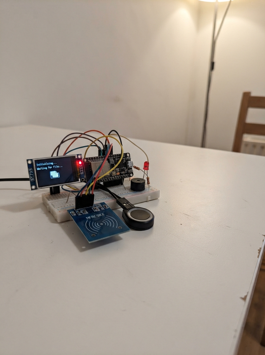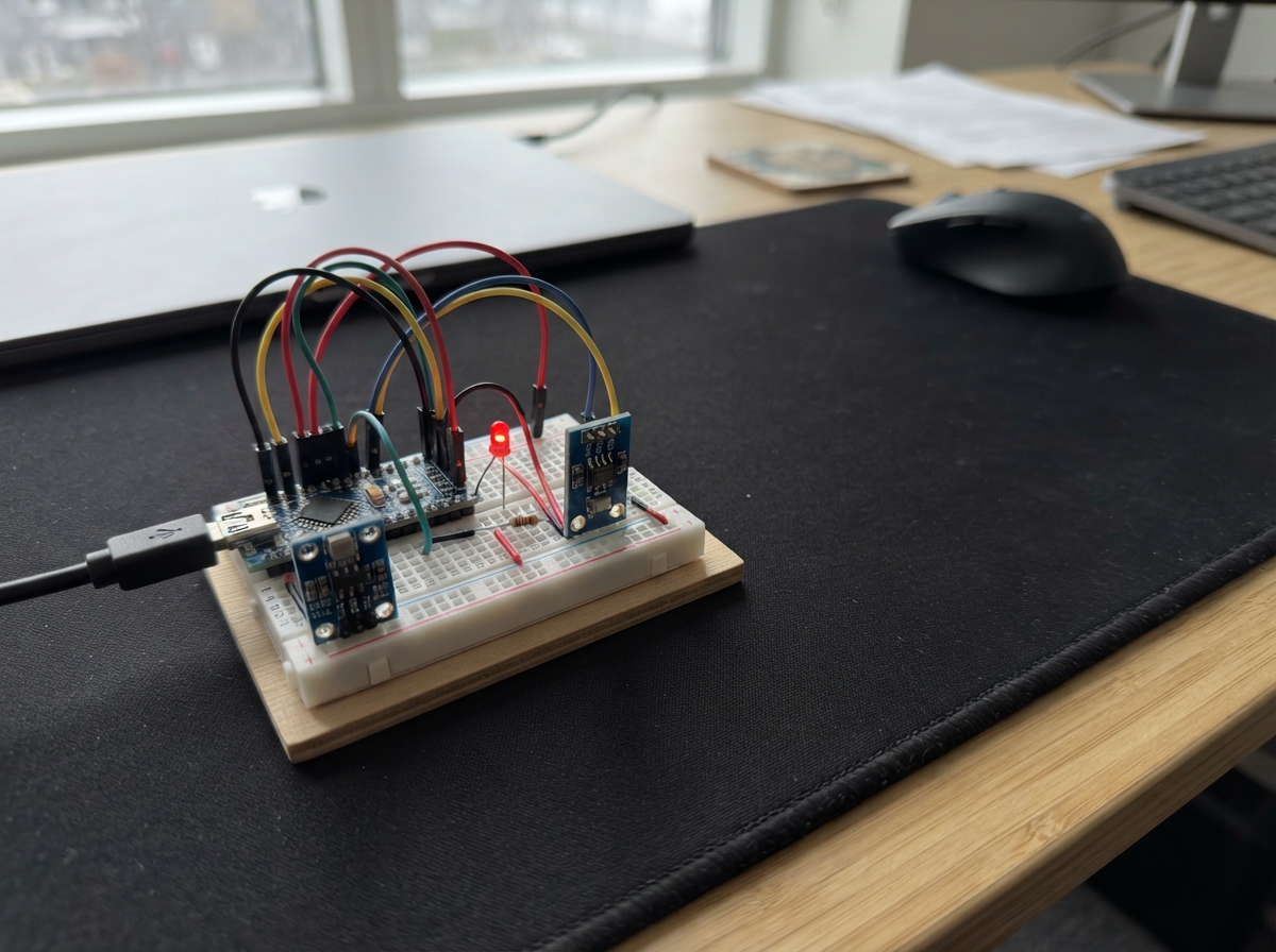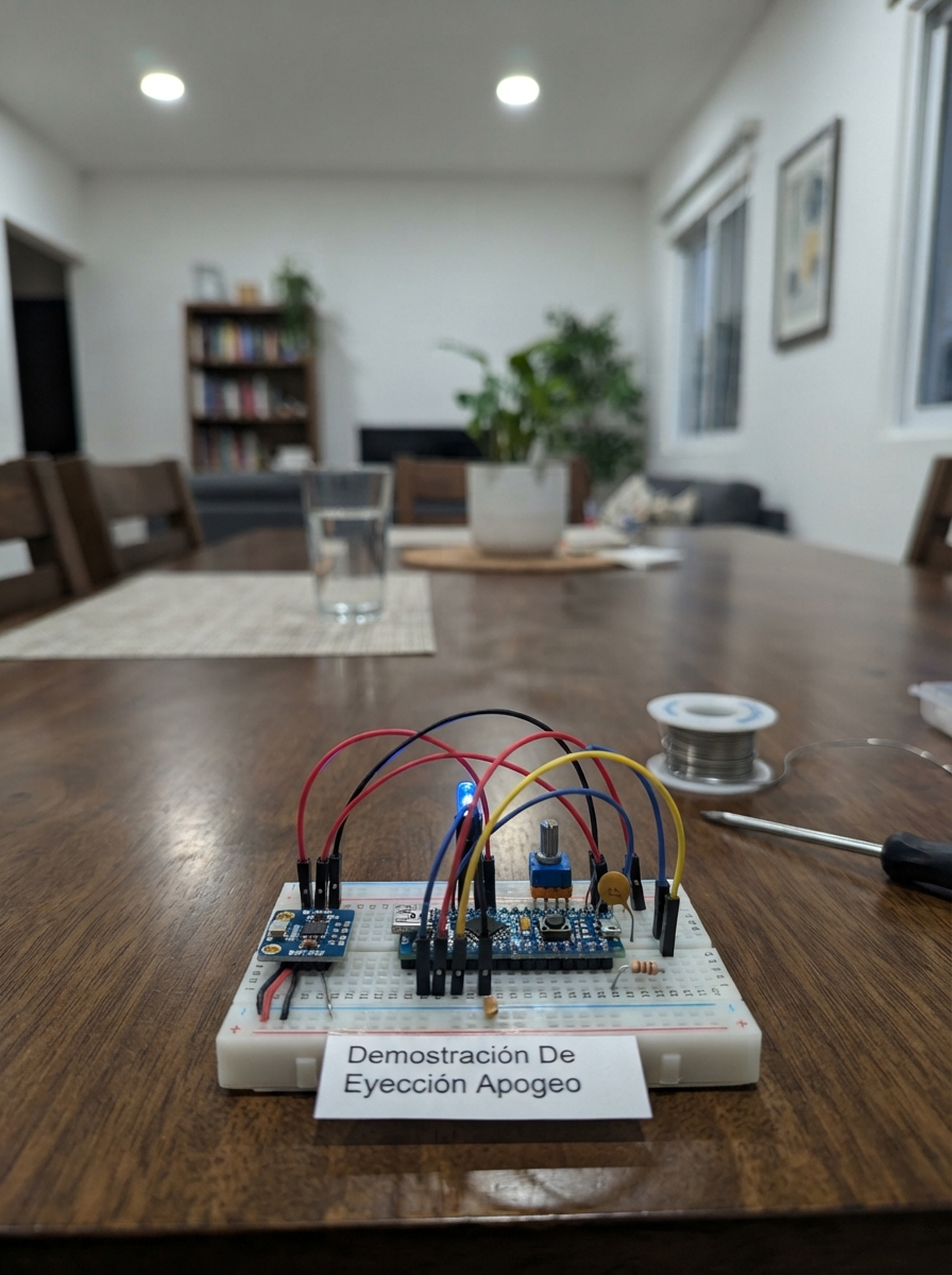
This apogee ejection demonstration shows how to detect when a model rocket reaches its peak altitude and trigger a pyrotechnic charge or other deployment mechanism. Built around an ESP32 microcontroller, a BMP280 barometric pressure sensor, and a potentiometer for setting the target altitude, the project simulates apogee detection with visual feedback via an LED and manual control through a push button.
The guide provides a complete wiring diagram, parts list, and step-by-step assembly instructions for building the sensor circuit and control interface. The included firmware runs in two modes: a simulated mode for testing and learning, and a live barometer mode that reads actual atmospheric pressure. Builders will learn how barometric sensors measure altitude, how to filter noisy sensor data, and how to safely arm and fire an ejection charge at the calculated apogee.
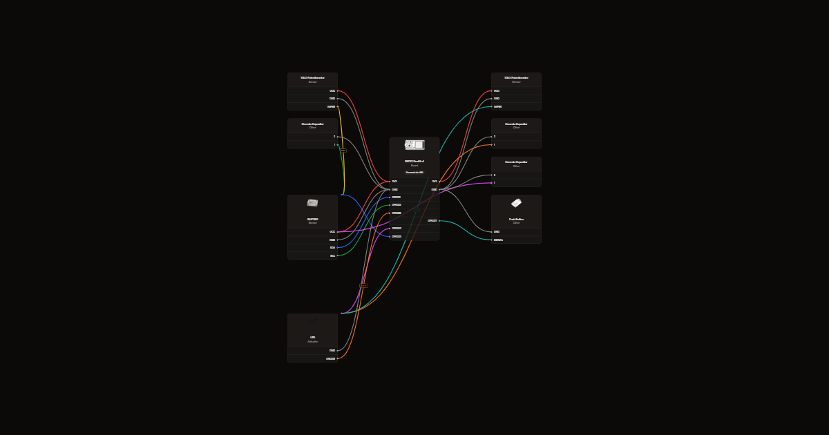
Wiring diagram
Gather all the parts
Assemble it in 6 steps
1. Preparar el montaje sin energía
Usa una protoboard, cables y un ESP32 DevKit V1. Desconecta USB mientras conectas. Esta maqueta solamente enciende un LED; no conectes cargas de eyección ni mecanismos.
- No es un controlador de vuelo ni un sistema de seguridad para un cohete real.
2. Conectar el sensor de altura
Usa un módulo BMP280 para 3.3 V con pines VCC, GND, SDA y SCL. VCC a 3V3 y GND a tierra; SDA a GPIO21 lleva los datos y SCL a GPIO22 lleva el reloj. Conecta cb de 100 nF entre VCC y GND cerca del módulo para estabilizar la alimentación.
- No uses 5 V en los potenciómetros ni en el sensor. No compres el chip BMP280 suelto.
3. Montar el ajuste de altura objetivo
Conecta los extremos del potenciómetro umbral a 3V3 y GND. El terminal central va a ru de 1 kΩ; el otro extremo de ru va a GPIO32. Conecta cu de 100 nF entre GPIO32 y GND. La perilla ajusta el objetivo entre 5 y 100 metros; la resistencia y el capacitor filtran cambios eléctricos rápidos.
4. Montar la altura simulada
Conecta los extremos del potenciómetro altura a 3V3 y GND. Su terminal central va a ra de 1 kΩ; el otro extremo va a GPIO33. Conecta ca de 100 nF entre GPIO33 y GND. La perilla simula de 0 a 120 metros para demostrar el funcionamiento sin lanzar nada.
5. Conectar la señal luminosa y el reinicio
GPIO25 va a rl de 330 Ω y después a la pata larga del LED rojo. La pata corta del LED va a GND. El pulsador conecta GPIO27 a GND al presionarlo. En un pulsador de cuatro patas, usa contactos de lados opuestos y comprueba que solo se unan al presionar.
- La resistencia limita la corriente y protege el LED. Pulsación corta reinicia; pulsación de dos segundos alterna simulación y medición real.
6. Revisar antes de alimentar
Comprueba que los rieles 3V3 y GND no estén unidos directamente. Mantén el BMP280 quieto, ventilado y fuera de corrientes de aire al iniciar una prueba real; el punto inicial será la referencia de cero metros.
- El LED queda encendido tras alcanzar el objetivo durante cinco muestras consecutivas. Reinicia con el pulsador para repetir. Para una prueba en el salón usa la altura simulada.
Review all connections
1. Connections between "barometro" and "ESP32"
2. Connections between "umbral" and "ESP32"
3. Connections between "ru" and "ESP32"
4. Connections between "cu" and "ESP32"
5. Connections between "altura" and "ESP32"
6. Connections between "ra" and "ESP32"
7. Connections between "ca" and "ESP32"
8. Connections between "cb" and "ESP32"
9. Connections between "rojo" and "ESP32"
10. Connections between "rl" and "ESP32"
11. Connections between "boton" and "ESP32"
Deploy the firmware
#include <Arduino.h>
#include <Wire.h>
#include <Adafruit_BMP280.h>
#include <math.h>
Adafruit_BMP280 bmp;
const int LED_PIN=25, BUTTON_PIN=27, THRESHOLD_PIN=32, HEIGHT_PIN=33;
bool simulated=true, sensorOK=false, armed=false, fired=false;
float referencePressure=0, filteredHeight=0;
unsigned long pressedAt=0,lastSample=0,lastPrint=0;
bool previousButton=false; int confirmations=0;
void resetDemo(){
 armed=false; fired=false; confirmations=0; filteredHeight=0;
 digitalWrite(LED_PIN,LOW);
 if(sensorOK){referencePressure=bmp.readPressure(); if(!isfinite(referencePressure)||referencePressure<30000) referencePressure=0;}
 Serial.println("Reinicio: bajar altura por debajo del umbral para habilitar.");
}
void setup(){
 pinMode(LED_PIN,OUTPUT); digitalWrite(LED_PIN,LOW);
 pinMode(BUTTON_PIN,INPUT_PULLUP); Serial.begin(115200);
 analogReadResolution(12); Wire.begin(21,22);
 sensorOK=bmp.begin(0x76); if(!sensorOK) sensorOK=bmp.begin(0x77);
 delay(500); resetDemo();
 Serial.println("DEMO LED. Inicio SIMULADO. Pulsacion corta: reiniciar; larga (2 s): cambiar modo.");
}
void loop(){
 unsigned long now=millis(); bool down=digitalRead(BUTTON_PIN)==LOW;
 if(down&&!previousButton) pressedAt=now;
 if(!down&&previousButton&&now-pressedAt>40){
   if(now-pressedAt>=2000) {simulated=!simulated; Serial.println(simulated?"Modo SIMULADO":"Modo BAROMETRO");}
   resetDemo();
 }
 previousButton=down;
 if(now-lastSample<100) return; lastSample=now;
 float threshold=5.0f+95.0f*analogRead(THRESHOLD_PIN)/4095.0f;
 float height=0; bool valid=true;
 if(simulated) height=120.0f*analogRead(HEIGHT_PIN)/4095.0f;
 else {
  valid=sensorOK&&referencePressure>0;
  if(valid){float p=bmp.readPressure(); valid=isfinite(p)&&p>30000&&p<110000;
   if(valid) height=44330.0f*(1.0f-powf(p/referencePressure,0.1903f));}
 }
 if(valid&&!down){
  filteredHeight=0.8f*filteredHeight+0.2f*height;
  if(!fired&&filteredHeight<threshold-2) armed=true;
  if(armed&&!fired&&filteredHeight>=threshold) confirmations++; else confirmations=0;
  if(confirmations>=5){fired=true; digitalWrite(LED_PIN,HIGH); Serial.println("SENAL DE EYECCION SIMULADA: LED ENCENDIDO");}
 }else confirmations=0;
 if(now-lastPrint>=500){lastPrint=now;
  Serial.printf("%s | altura %.1f m | umbral %.1f m | %s\n",simulated?"SIM":"BMP280",filteredHeight,threshold,
  !valid?"ERROR SENSOR: salida inhibida":fired?"ACTIVADO":armed?"LISTO":"BAJAR ALTURA");
 }
}
Remix this project
Make it yours in one click
Open a full copy of this project in your own Schematik workspace, diagram, code, parts, and assembly steps included. Swap the sensor, add features, or redesign the whole thing with AI. The author's original stays untouched.