Community project
Desk Air Quality Buddy
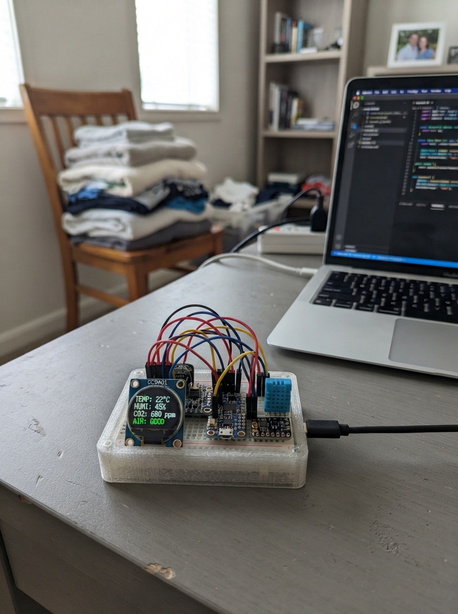
Desk Air Quality Buddy is a compact environmental monitor that displays temperature, humidity, sound levels, and motion detection on a vibrant 1.28-inch round display. Built around an ESP32 microcontroller, it combines a DHT11 humidity sensor, MPU-6050 motion detector, INMP441 microphone, and MAX98357A amplifier to create an all-in-one desk companion that keeps tabs on your workspace conditions.
This guide provides a complete wiring diagram, parts list, and step-by-step assembly instructions to get your Air Quality Buddy up and running. The included firmware handles sensor data collection, audio processing, and display rendering, with all configuration pins clearly defined for straightforward integration. Once assembled and powered, the device continuously monitors your environment and alerts you to humidity changes through audio feedback.
Wiring diagram

Gather all the parts
Assemble it in 6 steps
1. Place the parts without power
Put the ESP32-C3 Super Mini across the middle gap of the breadboard. Put the round screen at one end, and keep the microphone away from it. Leave the USB cable unplugged while you make every connection, so a misplaced wire cannot damage a part.
- Use one red breadboard power row for 3V3 and one blue or black row for GND.
- Do not connect the battery or wireless charger in this version; power the board only through its USB connector.
2. Connect the motion and humidity parts
Connect MPU-6050 VIN to ESP32 3V3 (power), MPU-6050 GND to GND (ground), MPU-6050 SDA to GPIO0 (data), and MPU-6050 SCL to GPIO1 (clock). Connect DHT11 VCC to 3V3 (power), DHT11 GND to GND (ground), and DHT11 DATA to GPIO3 (signal).
- If your DHT11 is the bare blue four-leg sensor rather than a three-pin board, add a 10 kΩ resistor between DATA and 3V3.
- Make sure 3V3 and GND are not swapped — swapped power can damage either sensor.
3. Connect the round screen
Connect display VCC to 3V3 (power), GND to GND (ground), SCK or CLK to GPIO4 (screen clock), MOSI or DIN to GPIO6 (screen data), CS to GPIO7 (screen select), DC to GPIO2 (screen command/data signal), RST to 3V3 (keeps the screen running), and BL or BLK to 3V3 (backlight power).
- On this display, a printed DIN or SDA label is the screen-data wire; it goes to GPIO6.
- Use 3V3 for the screen even if its label says it can accept 5V; the ESP32-C3 signal pins use 3.3V.
4. Connect the microphone and amplifier
Connect INMP441 VDD to 3V3 (power), GND to GND (ground), SCK to GPIO5 (sound timing), WS to GPIO20 (sound timing), SD to GPIO21 (sound signal), and L/R to GND (channel choice). Connect MAX98357A VIN to 3V3 (power), GND to GND (ground), BCLK to the same GPIO5 microphone SCK row (shared timing), LRC to the same GPIO20 microphone WS row (shared timing), and DIN to GPIO10 (beep signal).
- Use short wires around the microphone and amplifier. The microphone’s GPIO5 and GPIO20 wires each split to both audio boards.
- Do not connect the INMP441 or MAX98357A to 5V; both use 3.3V in this build.
5. Attach the small earphone speaker
Connect the earphone speaker's two wires only to MAX98357A SPK+ and SPK− (sound output). Either wire may be chosen first, but keep both connected only to those two amplifier terminals.
- The earphone speaker is for short nearby beeps, so it will be quieter than the large dock speaker.
- Do not connect either speaker wire to ESP32 GND or to any GPIO pin — that can damage the amplifier.
6. Power up and deploy
Check every 3V3 and GND wire once more, then plug the ESP32-C3 into USB. Press Deploy in Schematik. You should hear one short start-up beep and see the temperature, humidity, sound level, and movement status on the round screen.
- If there is no beep, check the amplifier VIN/GND and the two speaker wires before changing any code.
- Do not add the 370 mAh battery or wireless dock until its receiver, charger, and regulated output are designed as a separate safe power update.
Review all connections
1. Connections between "imu" and "ESP32"
2. Connections between "dht11" and "ESP32"
3. Connections between "microphone" and "ESP32"
4. Connections between "round_display" and "ESP32"
5. Connections between "audio_amp" and "ESP32"
Deploy the firmware
#include <Wire.h>
#include <SPI.h>
#include <DHT.h>
#include <Adafruit_GFX.h>
#include <Adafruit_GC9A01A.h>
#include <MPU6050.h>
#include <driver/i2s.h>
#include <math.h>

constexpr int I2C_SDA = 0;
constexpr int I2C_SCL = 1;
constexpr int DHT_PIN = 3;
constexpr int TFT_DC = 2;
constexpr int TFT_SCK = 4;
constexpr int AUDIO_BCLK = 5;
constexpr int TFT_MOSI = 6;
constexpr int TFT_CS = 7;
constexpr int AUDIO_DOUT = 10;
constexpr int AUDIO_WS = 20;
constexpr int MIC_DATA = 21;
constexpr int AUDIO_SAMPLE_RATE = 16000;

DHT dht(DHT_PIN, DHT11);
MPU6050 mpu;
Adafruit_GC9A01A display(TFT_CS, TFT_DC, -1);

bool imuReady = false;
float shownTemperature = NAN;
float shownHumidity = NAN;
uint32_t shownSound = UINT32_MAX;
bool shownMoving = false;
bool humidityAlarmActive = false;
unsigned long lastSampleMs = 0;

void setupAudio() {
  i2s_config_t config = {};
  config.mode = (i2s_mode_t)(I2S_MODE_MASTER | I2S_MODE_TX | I2S_MODE_RX);
  config.sample_rate = AUDIO_SAMPLE_RATE;
  config.bits_per_sample = I2S_BITS_PER_SAMPLE_32BIT;
  config.channel_format = I2S_CHANNEL_FMT_ONLY_LEFT;
  config.communication_format = I2S_COMM_FORMAT_STAND_I2S;
  config.intr_alloc_flags = 0;
  config.dma_buf_count = 4;
  config.dma_buf_len = 128;
  config.use_apll = false;
  config.tx_desc_auto_clear = true;
  config.fixed_mclk = 0;
  i2s_driver_install(I2S_NUM_0, &config, 0, nullptr);

  i2s_pin_config_t pins = {};
  pins.bck_io_num = AUDIO_BCLK;
  pins.ws_io_num = AUDIO_WS;
  pins.data_out_num = AUDIO_DOUT;
  pins.data_in_num = MIC_DATA;
  i2s_set_pin(I2S_NUM_0, &pins);
}

void playBeep(uint16_t frequency, uint16_t durationMs) {
  const int sampleCount = (AUDIO_SAMPLE_RATE * durationMs) / 1000;
  for (int i = 0; i < sampleCount; ++i) {
    float phase = 2.0f * PI * frequency * i / AUDIO_SAMPLE_RATE;
    int32_t sample = (int32_t)(sinf(phase) * 70000000.0f);
    size_t written = 0;
    i2s_write(I2S_NUM_0, &sample, sizeof(sample), &written, portMAX_DELAY);
  }
}

uint32_t readSoundLevel() {
  int32_t sample = 0;
  size_t bytesRead = 0;
  int64_t total = 0;
  int validSamples = 0;
  for (int i = 0; i < 48; ++i) {
    i2s_read(I2S_NUM_0, &sample, sizeof(sample), &bytesRead, 20 / portTICK_PERIOD_MS);
    if (bytesRead == sizeof(sample)) {
      total += abs(sample >> 14);
      ++validSamples;
    }
  }
  return validSamples ? total / validSamples : 0;
}

bool isMoving() {
  if (!imuReady) return false;
  int16_t ax, ay, az, gx, gy, gz;
  mpu.getMotion6(&ax, &ay, &az, &gx, &gy, &gz);
  return abs(gx) > 900 || abs(gy) > 900 || abs(gz) > 900;
}

void drawDashboard(float temperature, float humidity, uint32_t sound, bool moving) {
  display.fillScreen(GC9A01A_BLACK);
  display.setTextWrap(false);
  display.setTextColor(GC9A01A_CYAN);
  display.setTextSize(2);
  display.setCursor(48, 28);
  display.print("DESK");
  display.setCursor(43, 48);
  display.print("BUDDY");

  display.drawRoundRect(18, 78, 204, 42, 10, GC9A01A_BLUE);
  display.setTextColor(GC9A01A_WHITE);
  display.setTextSize(2);
  display.setCursor(31, 90);
  if (isnan(temperature) || isnan(humidity)) {
    display.print("DHT11 ERROR");
  } else {
    display.printf("%2.0fC  %2.0f%%", temperature, humidity);
  }

  display.drawRoundRect(18, 130, 204, 30, 8, GC9A01A_DARKGREY);
  display.setTextSize(1);
  display.setCursor(32, 140);
  display.printf("SOUND %lu", (unsigned long)sound);

  display.setTextColor(moving ? GC9A01A_YELLOW : GC9A01A_GREEN);
  display.setTextSize(2);
  display.setCursor(55, 184);
  display.print(moving ? "MOVING" : "STILL");
}

void setup() {
  Serial.begin(115200);
  Wire.begin(I2C_SDA, I2C_SCL);
  dht.begin();

  mpu.initialize();
  imuReady = mpu.testConnection();

  SPI.begin(TFT_SCK, -1, TFT_MOSI, TFT_CS);
  display.begin();
  display.setRotation(0);
  drawDashboard(NAN, NAN, 0, false);

  setupAudio();
  playBeep(1200, 90);
  Serial.println("DeskBuddy ready");
}

void loop() {
  if (millis() - lastSampleMs < 2000) return;
  lastSampleMs = millis();

  float temperature = dht.readTemperature();
  float humidity = dht.readHumidity();
  uint32_t sound = readSoundLevel();
  bool moving = isMoving();

  bool changed = isnan(temperature) != isnan(shownTemperature) ||
                 isnan(humidity) != isnan(shownHumidity) ||
                 (!isnan(temperature) && abs(temperature - shownTemperature) >= 0.5f) ||
                 (!isnan(humidity) && abs(humidity - shownHumidity) >= 1.0f) ||
                 abs((int32_t)sound - (int32_t)shownSound) >= 25 ||
                 moving != shownMoving;
  if (changed) {
    drawDashboard(temperature, humidity, sound, moving);
    shownTemperature = temperature;
    shownHumidity = humidity;
    shownSound = sound;
    shownMoving = moving;
  }

  bool humidityHigh = !isnan(humidity) && humidity >= 70.0f;
  if (humidityHigh && !humidityAlarmActive) {
    playBeep(850, 180);
  }
  humidityAlarmActive = humidityHigh;

  Serial.printf("Temp %.1f C, humidity %.1f%%, sound %lu, %s, MPU %s\n",
                temperature, humidity, (unsigned long)sound,
                moving ? "moving" : "still", imuReady ? "ready" : "not found");
}
Remix this project
Make it yours in one click
Open a full copy of this project in your own Schematik workspace — diagram, code, parts, and assembly steps included. Swap the sensor, add features, or redesign the whole thing with AI. The author's original stays untouched.