Community project
Drone-Mounted LoRa Loudspeaker
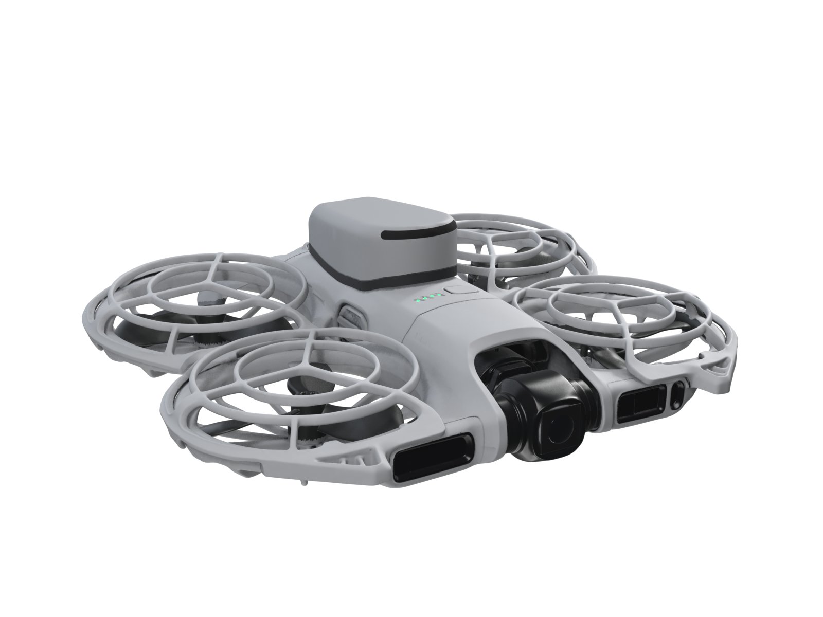
This project builds a lightweight LoRa-connected speaker pod designed to mount on drones or deploy in remote locations. It receives compressed voice packets over 915 MHz LoRa radio, decodes them using Codec2, and plays audio through a compact 2 W amplified speaker. The guide includes a complete wiring diagram, bill of materials, firmware source code, and step-by-step assembly instructions for integrating the Seeed Studio Wio-SX1262 module, MAX98357A amplifier, and LiPo battery into a flight-ready audio payload.
The pod runs on an ESP32 microcontroller with no Wi-Fi or Bluetooth enabled, keeping power consumption minimal and radio interference low. Assembly covers preparing the amplifier and radio boards, building a protected power harness, soldering signal connections, installing the speaker and antenna, and strain-relieving all components for vibration tolerance. Firmware handles LoRa packet reception, Codec2 audio decoding, I2S playback, volume control, battery monitoring, and low-power sleep modes.
Wiring diagram

Gather all the parts
Assemble it in 5 steps
1. Prepare the amplifier and boards
Remove the headers from max98357a_1, clean its pads, and solder only short 30 AWG silicone wires. Press wio_sx1262_1 fully onto the XIAO board-to-board connector; do not fit any headers anywhere.
- Do not pull on the SX1262 board after it is fitted; the small board-to-board connector can be damaged.
2. Make the protected power harness
Solder lipo_1 positive to the COM terminal of storage_switch_1 with a red wire, then solder the ON terminal to the XIAO BAT pad, max98357a_1 VIN, bulk_cap_1 positive, and the top 220 kΩ divider resistor. Solder lipo_1 negative to every GND point with black wire. Keep the red battery wire under 25 mm.
- Make sure LiPo positive and negative are not swapped — swapped battery wires can destroy the boards or heat the cell.
- Keep the 100 µF capacitor polarity correct: its marked negative side goes to GND.
3. Solder the signal wires
Solder blue BCLK from XIAO D1/GPIO2 to max98357a_1 BCLK, yellow WS from D4/GPIO5 to LRC, white DIN from D5/GPIO6 to DIN, and orange SD from D3/GPIO4 to SD. Solder button_1 between D2/GPIO3 and GND. Solder r_led_1 from D7/GPIO44 to the LED anode and the LED cathode to GND. Make the divider midpoint from both 220 kΩ resistors and c_divider_1 positive, then run a purple wire to D0/GPIO1.
- Keep every signal wire 45 mm or shorter and twist the BCLK, WS, and DIN wires loosely with a ground wire where possible.
- The LED only lights one way: its cathode mark goes to GND.
4. Install speaker and antenna
Solder the speaker leads directly to max98357a_1 SPK+ and SPK−, keeping the pair under 35 mm. Put speaker_1 above lipo_1 in the round front zone, facing upward. Use thin foam or hot glue only around the speaker rim to make an airtight seal to the baffle. Click antenna_1 onto the Wio U.FL socket and glue its flexible section vertically along the sealed tail-side wall, away from the LiPo and speaker magnet.
- Never connect either speaker lead to GND; the amplifier has two driven speaker outputs.
- Do not bend, pinch, or sharply crease the U.FL cable; it can break internally.
5. Pack and strain-relieve the pod
Lay lipo_1 flat on the front floor, place speaker_1 on top, and place the XIAO/Wio stack flat in the rear. Put max98357a_1 flat above the stack with insulating tape beneath it. Secure wires with small flexible adhesive spots, not hard glue on pads. Route usb_extension_1 from the XIAO USB-C connector to the tail opening and secure the FPC at both ends.
- Keep the front speaker volume sealed from the rear electronics volume; an air leak around the speaker rim greatly reduces sound.
- Do not cover the XIAO antenna area with the 915 MHz antenna or with metal tape.
Review all connections
1. Connections between "wio_sx1262_1" and "ESP32"
2. Connections between "lipo_1" and "ESP32"
3. Connections between "max98357a_1" and "ESP32"
4. Connections between "button_1" and "ESP32"
5. Connections between "r_divider_top_1" and "ESP32"
6. Connections between "r_divider_bottom_1" and "ESP32"
7. Connections between "c_divider_1" and "ESP32"
8. Connections between "r_led_1" and "ESP32"
9. Connections between "status_led_1" and "ESP32"
10. Connections between "bulk_cap_1" and "ESP32"
11. Connections between "usb_extension_1" and "ESP32"
12. Connections between "storage_switch_1" and "ESP32"
Deploy the firmware
#include <Arduino.h>
#include <SPI.h>
#include <RadioLib.h>
#include <codec2.h>
#include <WiFi.h>
#include "esp_bt.h"
#include "driver/i2s_std.h"
#include "driver/rtc_io.h"
#include "esp_sleep.h"
#include "esp_wifi.h"
#include "config.h"

// Neo2 Speaker Pod: 915–928 MHz Brazil LoRa receive pod. No Wi-Fi or Bluetooth is enabled.
static SX1262 radio = new Module(PIN_LORA_NSS, PIN_LORA_DIO1, PIN_LORA_RESET, PIN_LORA_BUSY);
static i2s_chan_handle_t txChan = nullptr;
static codec2* codec = nullptr;
static volatile bool radioIrq = false;
static uint16_t lastSequence = 0;
static uint8_t volumePct = 60;
static uint8_t stateCode = 0; // 0 idle, 1 stream, 2 siren
static uint32_t lastPacketMs = 0;
static int16_t previousFrame[160] = {0};
static bool ampEnabled = false;

constexpr uint8_t MAGIC = 0xA7;
constexpr uint8_t TYPE_VOICE = 0x01, TYPE_STOP = 0x03, TYPE_VOLUME = 0x04;
constexpr uint8_t TYPE_SIREN = 0x05, TYPE_PING = 0x06, TYPE_TELEMETRY = 0x10, TYPE_ACK = 0x11;

static uint16_t crc16(const uint8_t* p, size_t n) {
  uint16_t crc = 0xFFFF;
  while (n--) { crc ^= uint16_t(*p++) << 8; for (uint8_t i=0;i<8;i++) crc = (crc & 0x8000) ? (crc << 1) ^ 0x1021 : crc << 1; }
  return crc;
}
static void IRAM_ATTR onRadioIrq() { radioIrq = true; }
static void setAmp(bool on) {
  if (on == ampEnabled) return;
  digitalWrite(PIN_AMP_SD, on ? HIGH : LOW);
  ampEnabled = on;
  if (on) delay(20); // MAX98357A pre-roll
}
static float batteryVoltage() {
  uint32_t total = 0;
  for (int i=0;i<16;i++) { total += analogReadMilliVolts(PIN_VBAT); delay(1); }
  return (total / 16.0f) * 2.0f / 1000.0f; // 220k / 220k divider
}
static void writeMono16k(const int16_t* mono8k, size_t count) {
  // Duplicate each 8 kHz input sample; put it in LEFT I2S slot and silence RIGHT.
  int16_t out[320];
  for (size_t i=0;i<count;i++) {
    int32_t v = (int32_t)mono8k[i] * volumePct / 100;
    v = constrain(v, -29204, 29204); // -1 dBFS hard limiter
    out[i*2] = (int16_t)v;
    out[i*2+1] = 0;
  }
  size_t written = 0;
  i2s_channel_write(txChan, out, count * 2 * sizeof(int16_t), &written, portMAX_DELAY);
}
static void playCodecFrame(const uint8_t* bits) {
  int16_t pcm[160];
  codec2_decode(codec, pcm, const_cast<uint8_t*>(bits));
  memcpy(previousFrame, pcm, sizeof(pcm));
  setAmp(true);
  writeMono16k(pcm, 160);
}
static void stopAudio() { setAmp(false); stateCode = 0; }
static void sendTelemetry() {
  uint8_t packet[5 + 4 + 8 + 2];
  uint16_t mv = (uint16_t)(batteryVoltage() * 1000.0f);
  packet[0]=MAGIC; packet[1]=TYPE_TELEMETRY; packet[2]=lastSequence & 0xFF; packet[3]=lastSequence >> 8; packet[4]=12;
  packet[5]=POD_ID; packet[6]=POD_ID>>8; packet[7]=POD_ID>>16; packet[8]=POD_ID>>24;
  packet[9]=mv; packet[10]=mv>>8; packet[11]=(int8_t)radio.getRSSI(); packet[12]=(int8_t)(radio.getSNR()*4.0f);
  packet[13]=0; packet[14]=stateCode; packet[15]=volumePct;
  packet[16]=(batteryVoltage()<VBAT_WARN)?1:0;
  uint16_t c=crc16(packet,17); packet[17]=c; packet[18]=c>>8;
  digitalWrite(PIN_LORA_RF_SW, LOW);
  radio.transmit(packet, sizeof(packet));
  digitalWrite(PIN_LORA_RF_SW, HIGH);
  radio.startReceive();
}
static void handlePacket(uint8_t* p, size_t n) {
  if (n < 11 || p[0] != MAGIC || p[4] + 7 != n) return;
  uint16_t received = p[n-2] | (uint16_t(p[n-1]) << 8);
  if (crc16(p,n-2) != received) return;
  uint32_t id = uint32_t(p[5]) | uint32_t(p[6])<<8 | uint32_t(p[7])<<16 | uint32_t(p[8])<<24;
  if (id != POD_ID) return;
  lastSequence = p[2] | (uint16_t(p[3]) << 8);
  lastPacketMs = millis();
  const uint8_t* payload = p + 9; size_t length = p[4] - 4;
  if (p[1] == TYPE_VOICE && length >= 9 && batteryVoltage() >= VBAT_STOP) {
    // mode byte followed by Codec2 3200 frames, exactly 8 bytes/frame.
    for (size_t i=1; i+7<length; i+=8) playCodecFrame(payload+i);
    stateCode = 1;
  } else if (p[1] == TYPE_STOP) stopAudio();
  else if (p[1] == TYPE_VOLUME && length) volumePct = min<uint8_t>(MAX_VOLUME, payload[0]);
  else if (p[1] == TYPE_SIREN && length >= 2) stateCode = payload[0] ? 2 : 0;
  else if (p[1] == TYPE_PING) sendTelemetry();
}
static void serviceSiren() {
  static uint32_t phase = 0;
  if (stateCode != 2 || batteryVoltage() < VBAT_STOP) return;
  int16_t pcm[160];
  for (int i=0;i<160;i++) { float f = 1000.0f + 1000.0f * sinf(2.0f * PI * phase / 64000.0f); pcm[i]=(int16_t)(9000*sinf(2*PI*f*phase/16000.0f)); phase++; }
  setAmp(true); writeMono16k(pcm,160);
}
static void configureI2S() {
  i2s_chan_config_t chan = I2S_CHANNEL_DEFAULT_CONFIG(I2S_NUM_AUTO, I2S_ROLE_MASTER);
  i2s_new_channel(&chan, &txChan, nullptr);
  i2s_std_config_t cfg = {
    .clk_cfg = I2S_STD_CLK_DEFAULT_CONFIG(16000),
    .slot_cfg = I2S_STD_MSB_SLOT_DEFAULT_CONFIG(I2S_DATA_BIT_WIDTH_16BIT, I2S_SLOT_MODE_STEREO),
    .gpio_cfg = {.mclk=I2S_GPIO_UNUSED, .bclk=(gpio_num_t)PIN_I2S_BCLK, .ws=(gpio_num_t)PIN_I2S_WS, .dout=(gpio_num_t)PIN_I2S_DOUT, .din=I2S_GPIO_UNUSED, .invert_flags={false,false,false}}
  };
  i2s_channel_init_std_mode(txChan, &cfg); i2s_channel_enable(txChan);
}
void setup() {
  WiFi.mode(WIFI_OFF); esp_wifi_stop(); btStop(); esp_bt_controller_disable();
  Serial.begin(115200); delay(100);
  pinMode(PIN_AMP_SD, OUTPUT); pinMode(PIN_LED, OUTPUT); pinMode(PIN_BUTTON, INPUT_PULLUP); pinMode(PIN_LORA_RF_SW, OUTPUT);
  digitalWrite(PIN_LED, LOW); digitalWrite(PIN_LORA_RF_SW, HIGH); setAmp(false);
  analogReadResolution(12); analogSetPinAttenuation(PIN_VBAT, ADC_11db);
  configureI2S(); codec = codec2_create(CODEC2_MODE_3200);
  SPI.begin(PIN_LORA_SCK, PIN_LORA_MISO, PIN_LORA_MOSI, PIN_LORA_NSS);
  radio.setTCXO(1.8); radio.begin(LORA_MHZ, 500.0, 7, 5, 0x12, 14, 8, 1.8, false);
  radio.setDio2AsRfSwitch(true); radio.setCurrentLimit(140.0); radio.setDio1Action(onRadioIrq); radio.startReceive();
  esp_sleep_enable_ext0_wakeup((gpio_num_t)PIN_BUTTON, 0);
}
void loop() {
  float v = batteryVoltage();
  if (v < VBAT_SLEEP) { stopAudio(); rtc_gpio_hold_en((gpio_num_t)PIN_AMP_SD); esp_deep_sleep_start(); }
  if (radioIrq) { radioIrq=false; uint8_t raw[255]; size_t len=0; if (radio.readData(raw, sizeof(raw))==RADIOLIB_ERR_NONE) { len=raw[4]+7; if (len<=sizeof(raw)) handlePacket(raw,len); } radio.startReceive(); }
  if (stateCode == 1 && millis()-lastPacketMs > 1500) stopAudio();
  serviceSiren();
  if (stateCode == 0) { digitalWrite(PIN_LED, (millis()%2000)<80); }
  else digitalWrite(PIN_LED, HIGH);
  static uint32_t held=0; if (!digitalRead(PIN_BUTTON)) { if (!held) held=millis(); if (millis()-held>2000) { stopAudio(); rtc_gpio_hold_en((gpio_num_t)PIN_AMP_SD); esp_deep_sleep_start(); } } else held=0;
  static uint32_t telemetryAt=0; if (millis()-telemetryAt>1000) { telemetryAt=millis(); sendTelemetry(); }
  delay(2);
}
Remix this project
Make it yours in one click
Open a full copy of this project in your own Schematik workspace — diagram, code, parts, and assembly steps included. Swap the sensor, add features, or redesign the whole thing with AI. The author's original stays untouched.