Community project
ESP32 Camera Viewer
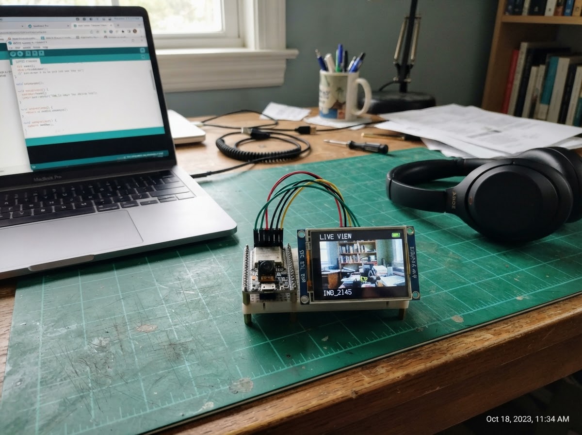
This project connects an OV2640 camera module to an ESP32-CAM board and displays the live video feed on a 240×320 ILI9341 TFT display. The camera captures frames at QVGA resolution and streams them to the small color screen in real time, making it useful for remote monitoring, robotics, or embedded vision applications.
The guide provides a complete wiring diagram showing how to connect the TFT display to the ESP32-CAM's SPI pins and control lines, a full parts list, and ready-to-compile Arduino firmware. Assembly takes about 15 minutes and requires only a soldering iron for secure connections. Troubleshooting tips help diagnose common camera initialization and display orientation issues.
Wiring diagram

Gather all the parts
Assemble it in 5 steps
1. Power down and identify the ESP32-CAM pins
Disconnect USB power. Use an AI Thinker ESP32-CAM with the OV2640 ribbon fully seated. This design uses its exposed microSD-header signals for the TFT, so leave the microSD socket empty.
- The camera is built into the ESP32-CAM; it is not a separate wired module.
- Use short jumper wires to reduce SPI display noise.
- Do not attach or use a microSD card: its bus is reassigned to the display.
- All ILI9341 signals must be 3.3 V logic. Do not use a 5 V-only TFT breakout.
2. Connect TFT power and ground
Connect ILI9341 VCC to the ESP32-CAM 3.3V pin and ILI9341 GND to an ESP32-CAM GND pin. If the module has a separate LED/BL input, connect it to 3.3V, or ensure its backlight jumper is enabled.
- A stable 5 V USB supply powering the ESP32-CAM is recommended because the camera and TFT together draw appreciable current.
- Never power the TFT logic from 5 V unless the particular module explicitly documents a regulator and 3.3 V level shifting.
3. Wire the shared SPI display bus
Connect TFT MOSI to GPIO13, TFT SCK/CLK to GPIO14, and TFT MISO to GPIO12. MISO is included because the selected touchscreen breakout exposes it, although this camera viewer does not read touch input.
- Match labels on the TFT carefully: MOSI may be called DIN, SDI, or SDA; SCK may be called CLK.
- Keep these wires short, especially SCK.
- GPIO12 and GPIO15 are ESP32 boot-strapping pins. Do not add pull-up or pull-down resistors to them, and power the board only after checking all connections.
4. Wire the TFT control lines
Connect TFT_CS to GPIO15, TFT_DC (sometimes labeled D/C or RS) to GPIO2, and TFT_RST/RESET to GPIO4. If the module includes touch pins, connect TOUCH_CS to GPIO1 only; leave TOUCH_IRQ disconnected. The firmware holds TOUCH_CS high so its controller remains inactive.
- GPIO4 also controls the ESP32-CAM onboard flash LED; its brief reset-level changes are normal.
- If your TFT has no touchscreen controller, leave its absent touch pins unconnected.
- GPIO1 is the ESP32-CAM serial TX pin. Avoid leaving a USB-to-serial adapter actively connected to this pin while the viewer is running, as it can interfere with the unused touch chip-select signal.
5. Check orientation, then power and deploy
Place the camera so its view is unobstructed. Power the ESP32-CAM through its normal USB/programming arrangement, then use Schematik’s Deploy button. The display should first show a startup message, then a live 320×240 landscape camera image.
- If the picture is rotated for your physical mounting, rotate the TFT or request a firmware orientation change.
- If the display remains blank, recheck VCC/GND, CS, DC, RST, and the MOSI/SCK connections first.
- Do not unplug or rewire while power is applied.
Review all connections
1. Connections between "ili9341_1" and "ESP32"
Deploy the firmware
#include <Arduino.h>
#include <SPI.h>
#include <Adafruit_GFX.h>
#include <Adafruit_ILI9341.h>
#include "esp_camera.h"

// ILI9341 write-only serial display on the ESP32-CAM microSD header pins.

// Forward declarations
void fatalScreen(const char *message);

constexpr int TFT_MOSI = 13;
constexpr int TFT_SCK = 14;
constexpr int TFT_CS = 15;
constexpr int TFT_DC = 2;
constexpr int TFT_RST = 4;

Adafruit_ILI9341 tft(TFT_CS, TFT_DC, TFT_RST);

// AI Thinker ESP32-CAM: OV2640 wiring is fixed on the board.
static camera_config_t cameraConfig = {
  .pin_pwdn = 32,
  .pin_reset = -1,
  .pin_xclk = 0,
  .pin_sccb_sda = 26,
  .pin_sccb_scl = 27,
  .pin_d7 = 35,
  .pin_d6 = 34,
  .pin_d5 = 39,
  .pin_d4 = 36,
  .pin_d3 = 21,
  .pin_d2 = 19,
  .pin_d1 = 18,
  .pin_d0 = 5,
  .pin_vsync = 25,
  .pin_href = 23,
  .pin_pclk = 22,
  .xclk_freq_hz = 20000000,
  .ledc_timer = LEDC_TIMER_0,
  .ledc_channel = LEDC_CHANNEL_0,
  .pixel_format = PIXFORMAT_RGB565,
  .frame_size = FRAMESIZE_QVGA,
  .jpeg_quality = 12,
  .fb_count = 1,
  .grab_mode = CAMERA_GRAB_LATEST,
  .fb_location = CAMERA_FB_IN_PSRAM
};

void fatalScreen(const char *message) {
  tft.fillScreen(ILI9341_BLACK);
  tft.setTextColor(ILI9341_RED);
  tft.setTextSize(2);
  tft.setCursor(8, 105);
  tft.println("Camera error");
  tft.setTextColor(ILI9341_WHITE);
  tft.setTextSize(1);
  tft.setCursor(8, 135);
  tft.println(message);
  while (true) {
    delay(1000);
  }
}

void setup() {
  SPI.begin(TFT_SCK, -1, TFT_MOSI, TFT_CS);
  tft.begin(27000000);
  tft.setRotation(1);  // 320 x 240 landscape
  tft.fillScreen(ILI9341_BLACK);
  tft.setTextColor(ILI9341_WHITE);
  tft.setTextSize(2);
  tft.setCursor(62, 108);
  tft.print("Starting camera...");

  if (!psramFound()) {
    fatalScreen("PSRAM was not detected.");
  }
  if (esp_camera_init(&cameraConfig) != ESP_OK) {
    fatalScreen("Check OV2640 ribbon cable.");
  }

  // The browser camera facade supplies placeholder frames and does not model
  // OV2640 sensor-register tuning. Keep the physical camera orientation setup.
#if defined(ARDUINO_ARCH_ESP32)
  sensor_t *sensor = esp_camera_sensor_get();
  sensor->set_vflip(sensor, 1);
  sensor->set_hmirror(sensor, 1);
#endif
  tft.fillScreen(ILI9341_BLACK);
}

void loop() {
  camera_fb_t *frame = esp_camera_fb_get();
  if (frame == nullptr) {
    delay(10);
    return;
  }

  // QVGA RGB565 exactly matches the TFT in landscape. Big-endian output
  // matches the OV2640 buffer order and avoids a slow per-pixel conversion.
  tft.startWrite();
  tft.setAddrWindow(0, 0, 320, 240);
  tft.writePixels(reinterpret_cast<uint16_t *>(frame->buf), 320UL * 240UL, true, true);
  tft.endWrite();
  esp_camera_fb_return(frame);
}
Remix this project
Make it yours in one click
Open a full copy of this project in your own Schematik workspace — diagram, code, parts, and assembly steps included. Swap the sensor, add features, or redesign the whole thing with AI. The author's original stays untouched.