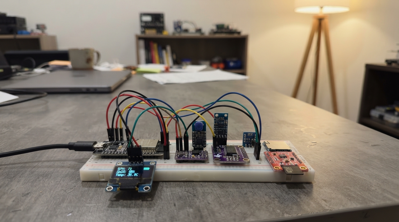
This ESP32 vital signs monitor captures heart rate, blood oxygen saturation, body temperature, and ECG waveforms on a bench prototype. The project combines a MAX30102 optical sensor for pulse oximetry, an MLX90614 infrared thermometer, an AD8232 ECG simulator interface, and a DS3231 real-time clock to log timestamped measurements to a microSD card. The SSD1306 OLED display shows live readings while the ADS1115 ADC conditions the ECG signal for analysis.
This guide provides a complete wiring diagram, parts list, and step-by-step assembly instructions for building the prototype on a breadboard. The included Arduino firmware initializes all sensors, manages I2C and SPI communication, calculates oxygen saturation and heart rate from raw optical data, and logs all vital signs with timestamps to CSV files for later review. Builders will learn how to integrate multiple health sensors with an ESP32 and create a data-logging system suitable for educational projects and sensor evaluation.
Wiring diagram
Gather all the parts
Assemble it in 6 steps
1. Keep this a bench prototype
Use USB power only. Never attach electrodes or leads to a person or animal. Connect the AD8232 input only to a purpose-built ECG signal simulator using its manufacturer-approved lead adapter and instructions; otherwise leave RA, LA, RL and the jack unconnected.
- This circuit has no verified patient protection. Ordinary function generators are not interchangeable with an ECG simulator.
2. Check the module power requirements
Unplug USB. Use MAX30102 and MLX90614 breakout modules that operate from 3.3 V, and a microSD adapter explicitly supporting 3.3 V supply and logic. A 5 V-only SD module with an onboard regulator is not suitable for this wiring. Leave the RTC coin-cell holder empty for the first build, especially on boards with charging circuits. The RTC VIN pin may be labelled VCC on your module.
- Do not connect a 5 V pull-up to the ESP32 data lines. Leave battery charging and boost circuits disconnected.
3. Connect shared power and data
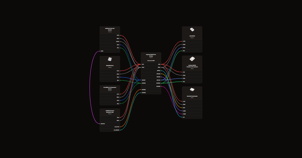
Connect OLED VCC, MAX30102 VCC, MLX90614 VCC, RTC VIN and ADS1115 VDD to 3V3. Connect each GND to ESP32 GND. Connect each SDA to GPIO21 for data and each SCL to GPIO22 for the shared clock. Connect ADS1115 ADDR to GND to select address 0x48. Keep wires short; breakouts must have I2C pull-ups to 3.3 V. Do not add extra pull-ups blindly because several modules may already include them.
4. Wire the bench ECG output
Connect AD8232 3.3V to 3V3, GND to GND, OUTPUT to ADS1115 A0 (AIN0), LO+ to GPIO32 and LO- to GPIO33. Leave SDN unconnected as in the SparkFun hookup. These are simulator-only bench connections. Unused ADS1115 inputs remain unconnected.
- The ADC measures module output voltage
- not a calibrated electrode voltage. No body connection is permitted.
5. Add storage
Connect the compatible SD adapter VCC to 3V3, GND to GND, SCK to GPIO18 (clock), MISO to GPIO19 (card data out), MOSI to GPIO23 (card data in), and CS to GPIO4 (card select). Insert a FAT32-formatted microSD card with power unplugged. Keep SPI wires short. Check that the ESP32 3.3 V regulator can supply the modules including SD current peaks; do not continue if resets or overheating occur.
6. Finish and inspect
Check all power polarity and printed pin labels before applying USB power. Keep exposed conductors away from skin; only the insulated optical sensor face may touch a finger, and temperature sensing is non-contact. Use an enclosure with an opening for the optical window. Disconnect USB before removing the SD card; up to two seconds of buffered records may be lost. The HX711, LM358, charger, booster, unverified regulator, IRLZ44N, buzzer, LED and disposable electrodes are not used in this build.
- This is a learning prototype
- not a diagnostic device or medical alarm.
Review all connections
1. Connections between "oled" and "ESP32"
2. Connections between "pulse" and "ESP32"
3. Connections between "temperature" and "ESP32"
4. Connections between "rtc" and "ESP32"
5. Connections between "adc" and "ESP32"
6. Connections between "ecg" and "ESP32"
7. Connections between "sd" and "ESP32"
Deploy the firmware
#include <Arduino.h>
#include <Wire.h>
#include <SPI.h>
#include <SD.h>
#include <Adafruit_GFX.h>
#include <Adafruit_SSD1306.h>
#include <Adafruit_MLX90614.h>
#include <Adafruit_ADS1X15.h>
#include <RTClib.h>
#include <MAX30105.h>
#include <spo2_algorithm.h>
#include <math.h>

// BENCH PROTOTYPE ONLY. AD8232 connects only to a purpose-built ECG simulator.
Adafruit_SSD1306 screen(128,64,&Wire,-1);
Adafruit_MLX90614 thermometer;
Adafruit_ADS1115 adc;
RTC_DS3231 rtc;
MAX30105 pulse;
File logFile;
bool oledOK, tempOK, adcOK, rtcOK, pulseOK, sdOK;
bool simulated=false, rtcValid=false;
uint32_t ir[100],red[100],lastIR=0,lastRed=0;
int fill=0;
int32_t oxygen=0,heart=0;
int8_t oxygenValid=0,heartValid=0;
float objectC=NAN,ambientC=NAN,ecgV=NAN;
int leadOff=1;
uint32_t lastECG=0,lastSlow=0,lastFlush=0,lastOptical=0;
String previousDisplay;

void openLog() {
  if(logFile) {logFile.flush(); logFile.close();}
  sdOK=false;
  for(int i=0;i<1000;i++) {
    char path[24]; snprintf(path,sizeof(path),"/%c%03d.csv",simulated?'S':'R',i);
    if(SD.exists(path)) continue;
    logFile=SD.open(path,FILE_WRITE);
    if(logFile) {
      sdOK=true;
      logFile.println("mode,ms,unix_time,rtc_valid,ecg_output_V,lead_off,red_raw,ir_raw,heart_bpm,spo2_percent,object_C,ambient_C");
      Serial.print("Logging: ");Serial.println(path);
    }
    break;
  }
}
void setMode(bool sim) {
  simulated=sim; fill=0; heartValid=oxygenValid=0;
  heart=oxygen=0;lastIR=lastRed=0;ecgV=objectC=ambientC=NAN;
  previousDisplay="";
  if(sdOK) openLog();
  Serial.println(sim?"SIMULATED DATA MODE":"REAL SENSOR MODE: ECG SIMULATOR ONLY");
}
void setup() {
  Serial.begin(115200);
  pinMode(32,INPUT);pinMode(33,INPUT);
  Wire.begin(21,22);Wire.setClock(100000);Wire.setTimeOut(50);
  Wire.beginTransmission(0x3C);
  oledOK=Wire.endTransmission()==0 && screen.begin(SSD1306_SWITCHCAPVCC,0x3C);
  if(oledOK) {screen.setTextSize(1);screen.setTextColor(SSD1306_WHITE);}
  tempOK=thermometer.begin();
  rtcOK=rtc.begin();
  rtcValid=rtcOK && !rtc.lostPower();
  // Do not invent a date. Set clock explicitly using T followed by Unix seconds.
  adcOK=adc.begin(0x48);
  if(adcOK) {adc.setGain(GAIN_ONE);adc.setDataRate(RATE_ADS1115_860SPS);}
  pulseOK=pulse.begin(Wire,100000);
  if(pulseOK) pulse.setup(0x1F,4,2,100,411,4096); // 100 / 4 = 25 optical samples/s
  SPI.begin(18,19,23,4);
  sdOK=SD.begin(4,SPI,4000000);
  if(sdOK) openLog();
  Serial.printf("OLED=%d MAX30102=%d MLX90614=%d ADS1115=%d RTC=%d RTC_VALID=%d SD=%d\n",oledOK,pulseOK,tempOK,adcOK,rtcOK,rtcValid,sdOK);
  Serial.println("s: simulated data; r: real sensors; f: flush SD. T<Unix seconds> sets RTC.");
  Serial.println("No electrodes on a person. Values are not medical measurements.");
}
void loop() {
  static String command;
  while(Serial.available()) {
    char c=Serial.read();
    if(c=='\n'||c=='\r') {
      if(command=="s")setMode(true);
      else if(command=="r")setMode(false);
      else if(command=="f" && logFile)logFile.flush();
      else if(command.startsWith("T")&&rtcOK) {
        uint32_t t=strtoul(command.c_str()+1,nullptr,10);
        if(t>=1704067200UL && t<4102444800UL) {rtc.adjust(DateTime(t));rtcValid=true;}
      }
      command="";
    } else if(command.length()<32) command+=c;
  }
  uint32_t now=millis();
  if(pulseOK) {
    pulse.check();
    while(pulse.available()) {
      uint32_t i=pulse.getFIFOIR(),r=pulse.getFIFORed();pulse.nextSample();
      if(simulated)continue;
      lastOptical=now;lastIR=i;lastRed=r;
      if(i<50000) {fill=0;heartValid=oxygenValid=0;continue;}
      ir[fill]=i;red[fill]=r;fill++;
      if(fill==100) {
        maxim_heart_rate_and_oxygen_saturation(ir,100,red,&oxygen,&oxygenValid,&heart,&heartValid);
        if(heart<30||heart>220)heartValid=0;
        if(oxygen<0||oxygen>100)oxygenValid=0;
        memmove(ir,ir+25,75*sizeof(uint32_t));memmove(red,red+25,75*sizeof(uint32_t));fill=75;
      }
    }
  }
  if(!simulated && now-lastOptical>2000) {heartValid=oxygenValid=0;lastIR=lastRed=0;fill=0;}
  // Best-effort 100 Hz ECG-output recording, not diagnostic ECG timing.
  if(now-lastECG>=10) {
    lastECG=now;
    if(simulated) {
      float p=(now%833)/833.0f;
      ecgV=1.65f+0.5f*expf(-powf((p-.4f)/.015f,2))+.05f*sinf(p*6.283185f);
      leadOff=0;heart=72;oxygen=98;heartValid=oxygenValid=1;
      lastIR=90000+(int)(1000*sinf(p*6.283185f));lastRed=80000+(int)(800*sinf(p*6.283185f));
    } else {
      leadOff=digitalRead(32)||digitalRead(33);
      ecgV=adcOK?adc.computeVolts(adc.readADC_SingleEnded(0)):NAN;
    }
    if(sdOK && logFile) {
      char row[220];
      unsigned long epoch=rtcValid?rtc.now().unixtime():0;
      snprintf(row,sizeof(row),"%s,%lu,%lu,%d,%.5f,%d,%lu,%lu,%ld,%ld,%.2f,%.2f\n",simulated?"SIM":"REAL",(unsigned long)now,epoch,rtcValid,ecgV,leadOff,(unsigned long)lastRed,(unsigned long)lastIR,(long)(heartValid?heart:-1),(long)(oxygenValid?oxygen:-1),objectC,ambientC);
      if(logFile.print(row)==0) {sdOK=false;Serial.println("SD write failed");}
    }
  }
  if(now-lastSlow>=1000) {
    lastSlow=now;
    objectC=simulated?36.7f:(tempOK?thermometer.readObjectTempC():NAN);
    ambientC=simulated?24.0f:(tempOK?thermometer.readAmbientTempC():NAN);
    String text=simulated?"SIMULATION ONLY\n":"BENCH / NOT MEDICAL\n";
    text+="HR:"+String(heartValid?String(heart):"--")+" O2:"+String(oxygenValid?String(oxygen):"--")+"%\n";
    text+="Surface:"+String(objectC,1)+"C\n";
    text+="ECG:"+String(ecgV,3)+"V L:"+String(leadOff)+"\n";
    text+="SD:"+String(sdOK?"REC":"FAIL")+" RTC:"+String(rtcValid?"OK":"UNSET")+"\n";
    text+="s=sim r=real (USB)";
    Serial.println(text);
    if(oledOK && text!=previousDisplay) {screen.clearDisplay();screen.setCursor(0,0);screen.print(text);screen.display();previousDisplay=text;}
  }
  if(now-lastFlush>=2000) {lastFlush=now;if(logFile)logFile.flush();}
  delay(1);
}
Remix this project
Make it yours in one click
Open a full copy of this project in your own Schematik workspace, diagram, code, parts, and assembly steps included. Swap the sensor, add features, or redesign the whole thing with AI. The author's original stays untouched.