Community project
ESP32 Connection Validator
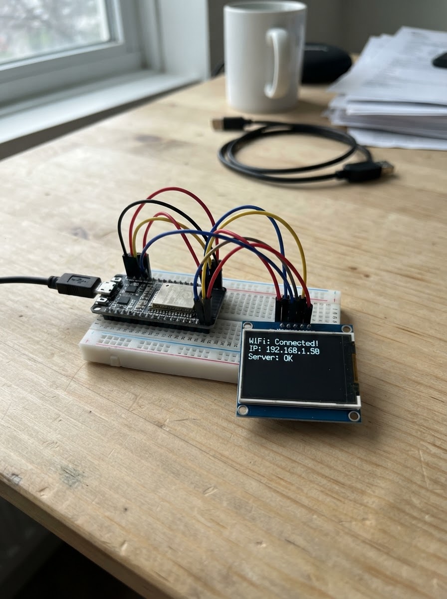
The ESP32 Connection Validator is a digital clock display project that demonstrates reliable communication between an ESP32 microcontroller and a 2.0-inch ST7789 TFT display. The project features a retro-styled interface with warm orange and black colors, displaying elapsed time in HH:MM format with a decorative clock face.
This guide provides a complete parts list, wiring diagram showing all SPI and control pin connections, and step-by-step assembly instructions. The included firmware uses the Adafruit GFX and ST7789 libraries to render graphics and update the time display efficiently, making this an ideal starting point for learning display integration with ESP32 projects.
Wiring diagram
Gather all the parts
Assemble it in 5 steps
1. Desconecta la alimentación
Desenchufa el cable USB-C del ESP32 antes de mover cables. Así evitas que un cable suelto toque otro pin y dañe la pantalla.
- Coloca la pantalla con las etiquetas de los pines a la vista.
- No conectes ni quites los cables mientras el ESP32 esté alimentado; un cruce accidental puede dañar la pantalla o la placa.
2. Conecta la alimentación de la pantalla
Conecta el cable morado de VCC al pin 3V3 del ESP32 (alimentación). Conecta el cable blanco de GND a un pin GND del ESP32 (tierra).
- Usa el pin marcado 3V3, no el de 5V.
- Comprueba que morado y blanco no estén intercambiados.
- No conectes VCC a 5V para este test: la pantalla y las señales del ESP32 trabajan a 3,3 V; una alimentación equivocada puede dañarla.
3. Conecta los dos cables principales de imagen
Conecta el cable verde DIN a D23 (datos) y el cable naranja CLK a D18 (ritmo de los datos). Estos dos cables llevan la imagen a la pantalla.
- DIN también puede llamarse MOSI en algunos esquemas.
- Verde → D23 (datos), naranja → D18 (reloj).
- Si DIN y CLK quedan intercambiados, la pantalla no podrá recibir una imagen válida.
4. Conecta los cables de control
Conecta amarillo CS a D5 (selecciona la pantalla), azul DC a D16 (distingue órdenes de píxeles), café RST a D4 (reinicia la pantalla) y gris BL a D15 (enciende la luz trasera).
- Azul va a D16; en tu mensaje aparecía como “D116”, pero el pin correcto es D16.
- Amarillo → D5 (selección), azul → D16 (órdenes), café → D4 (reinicio), gris → D15 (luz).
- D5 y D15 también participan durante el arranque del ESP32. Mantén las conexiones firmes y no mantengas pulsado BOOT al encender.
5. Revisa y enciende
Comprueba los ocho cables una vez más y conecta el ESP32 al PC con USB-C. La pantalla debe encender su luz trasera; después de desplegar el programa mostrará colores sólidos y texto que cambian cada dos segundos.
- Si la luz trasera no se enciende, revisa primero gris BL, morado VCC y blanco GND.
- Si se ilumina pero no aparecen colores, revisa verde DIN y naranja CLK.
- Asegúrate de que VCC y GND no estén intercambiados: invertirlos puede dañar la pantalla.
Review all connections
1. Connections between "lcd_1_83_test" and "ESP32"
Deploy the firmware
#include <Arduino.h>
#include <SPI.h>
#include <Adafruit_GFX.h>
#include <Adafruit_ST7789.h>


// Forward declarations
void drawClockFace();
void drawTime();

constexpr int TFT_MOSI = 23;
constexpr int TFT_SCLK = 18;
constexpr int TFT_CS = 5;
constexpr int TFT_DC = 16;
constexpr int TFT_RST = 4;
constexpr int TFT_BL = 15;
constexpr uint16_t TFT_WIDTH = 240;
constexpr uint16_t TFT_HEIGHT = 280;

// Naranja cálido estilo retro y texto negro.
const uint16_t VINTAGE_ORANGE = 0xCB85;
const uint16_t INK_BLACK = ST77XX_BLACK;

Adafruit_ST7789 tft(TFT_CS, TFT_DC, TFT_RST);
unsigned long lastSecond = 0;
uint32_t elapsedSeconds = 0;

void drawClockFace() {
  tft.fillScreen(VINTAGE_ORANGE);
  tft.drawRect(4, 4, TFT_WIDTH - 8, TFT_HEIGHT - 8, INK_BLACK);
  tft.drawRect(8, 8, TFT_WIDTH - 16, TFT_HEIGHT - 16, INK_BLACK);

  tft.setTextColor(INK_BLACK);
  tft.setTextSize(2);
  tft.setCursor(40, 45);
  tft.print("RELOJ");
  tft.setCursor(27, 70);
  tft.print("DIGITAL");

  tft.drawFastHLine(20, 100, 200, INK_BLACK);
  tft.setTextSize(1);
  tft.setCursor(59, 245);
  tft.print("PRUEBA DE PANTALLA");
}

void drawTime() {
  const uint32_t totalMinutes = elapsedSeconds / 60;
  const uint8_t hours = (12 + totalMinutes / 60) % 24;
  const uint8_t minutes = totalMinutes % 60;
  char timeText[6];
  snprintf(timeText, sizeof(timeText), "%02u:%02u", hours, minutes);

  // Solo se borra y redibuja el área de los números que cambia.
  tft.fillRect(10, 118, 220, 58, VINTAGE_ORANGE);
  tft.setTextColor(INK_BLACK);
  tft.setTextSize(7);
  tft.setCursor(15, 122);
  tft.print(timeText);
}

void setup() {
  pinMode(TFT_BL, OUTPUT);
  digitalWrite(TFT_BL, HIGH);
  SPI.begin(TFT_SCLK, -1, TFT_MOSI, TFT_CS);
  tft.init(TFT_WIDTH, TFT_HEIGHT);
  tft.setRotation(0);

  drawClockFace();
  drawTime();
  lastSecond = millis();
}

void loop() {
  const unsigned long now = millis();
  if (now - lastSecond >= 1000) {
    lastSecond += 1000;
    ++elapsedSeconds;
    if (elapsedSeconds % 60 == 0) {
      drawTime();
    }
  }
}
Remix this project
Make it yours in one click
Open a full copy of this project in your own Schematik workspace — diagram, code, parts, and assembly steps included. Swap the sensor, add features, or redesign the whole thing with AI. The author's original stays untouched.