Community project
ESP32 Plane Radar Map
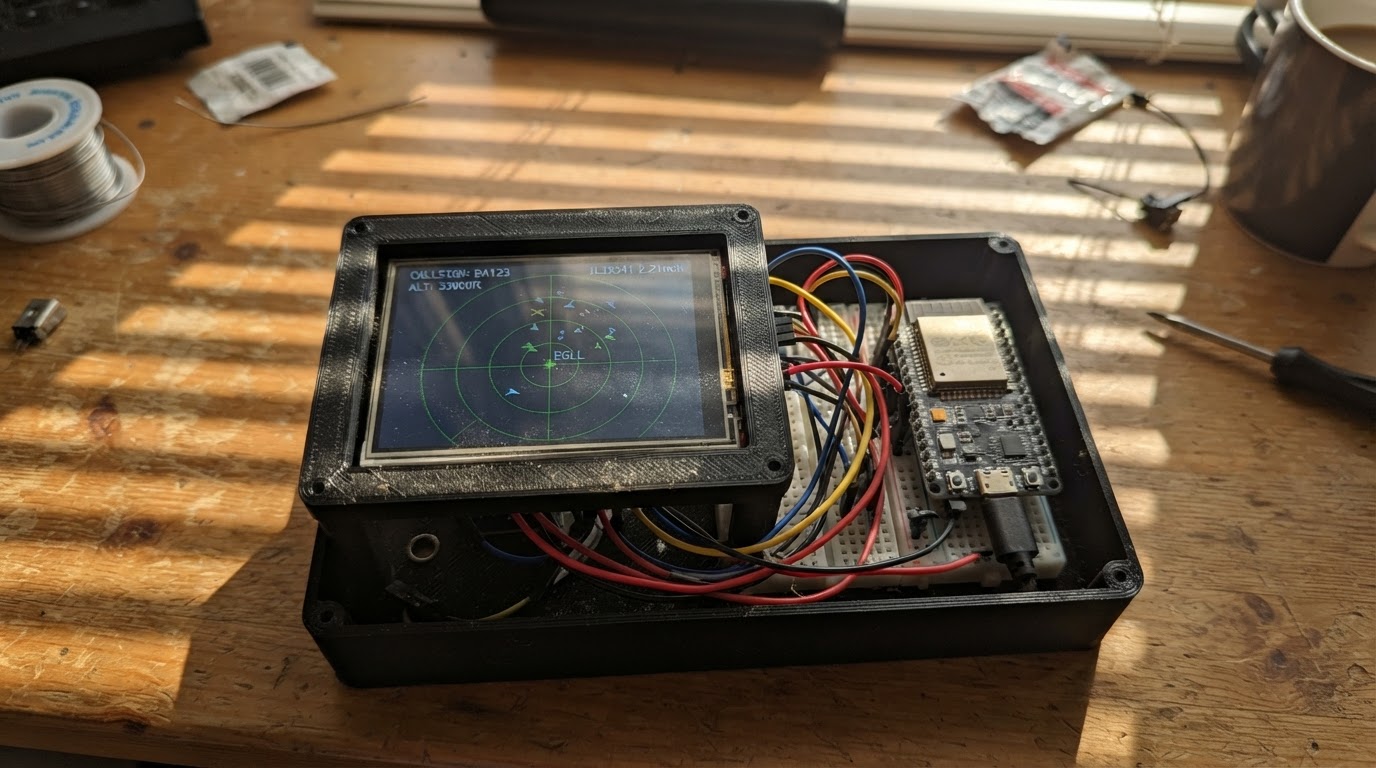
This project turns an ESP32 microcontroller and ILI9341 touchscreen into a live aircraft radar map. The display connects to a public aircraft tracking API over WiFi to fetch real-time flight data within a configurable radius, then plots aircraft positions, altitudes, and callsigns on an interactive map centered on any location worldwide.
The guide provides a complete wiring diagram showing how to connect the TFT display and touch controller to the ESP32's SPI pins, a full parts list, ready-to-deploy firmware with WiFi and API integration, and step-by-step assembly instructions. Customize the map center coordinates and search radius in the code, then watch live aircraft appear on your screen as they fly overhead.
Wiring diagram

Gather all the parts
Assemble it in 5 steps
1. Keep the power off while wiring
Unplug the ESP32 USB cable. Put the ESP32 and the 2.8-inch screen on a breadboard or place them side by side with the labels facing up, so you can read every pin name.
- Use short jumper wires for the three fast screen wires labeled SCK, MOSI, and MISO; shorter wires make the picture more reliable.
- Do not connect the USB cable until the power and ground wires have been checked; a misplaced wire can heat parts or damage the screen.
2. Give the screen safe power
Connect the screen VCC pin to the ESP32 3V3 pin (power). Connect the screen GND pin to an ESP32 GND pin (ground). Connect TFT_BL to 3V3 (backlight power).
- The screen and ESP32 both use 3.3 volts here, so do not use the ESP32 VIN or 5V pin for VCC.
- Make sure VCC and GND are not swapped — swapped power can damage the screen.
3. Connect the shared picture wires
Connect screen SCK to ESP32 GPIO18 (clock). Connect screen MOSI to ESP32 GPIO23 (picture data). Connect screen MISO to ESP32 GPIO19 (touch data). These three wires are shared by the display and its touch layer.
- Follow the printed names on your screen module; some modules call MOSI “SDI” and call MISO “SDO.”
- Do not move these wires to random ESP32 pins without changing the firmware, because the screen would no longer receive its picture data.
4. Connect the screen control wires
Connect TFT_CS to ESP32 GPIO4 (selects the picture screen). Connect TFT_DC to GPIO27 (marks commands versus picture data). Connect TFT_RST to GPIO26 (resets the screen when starting). Connect TOUCH_CS to GPIO25 (selects the touch layer). Leave TOUCH_IRQ unconnected (it is not needed).
- Each control wire has a different job, so keep the GPIO numbers distinct and check them one at a time.
- Do not use the ESP32 pins marked GPIO0, GPIO2, GPIO5, GPIO12, or GPIO15 for these wires; those pins can affect whether the board starts.
5. Power and use the radar
Check every wire against the earlier steps, then plug the ESP32 into your computer with USB. Edit the Wi-Fi name, Wi-Fi password, and map-center latitude and longitude near the top of the firmware if needed. Press Deploy in Schematik. After it starts, tap anywhere on the screen to request a fresh aircraft view; otherwise it refreshes about every 15 seconds.
- The first built-in map center is London Heathrow. Replace the two map-center numbers with the latitude and longitude of the place you want to watch.
- If no planes appear, first confirm the ESP32 has joined a 2.4 GHz Wi-Fi network and that there are aircraft-feed receivers near your chosen map center.
- Never enter a Wi-Fi password into a shared project if you do not want other project viewers to see it.
Review all connections
1. Connections between "radar_tft" and "ESP32"
Deploy the firmware
#include <Arduino.h>
#include <WiFi.h>
#include <WiFiClientSecure.h>
#include <SPI.h>
#include <ArduinoJson.h>
#include <Adafruit_GFX.h>
#include <Adafruit_ILI9341.h>
#include <XPT2046_Touchscreen.h>

// Change these three settings before deploying.

// Hoisted type definitions
struct Aircraft {
  float latitude;
  float longitude;
  float altitudeFeet;
  float speedKnots;
  float trackDegrees;
  char callsign[10];
};


// Forward declarations
void drawCentered(const String &text, int y, uint16_t color, uint8_t size);
void drawRadar();
bool connectWiFi();
bool fetchAircraft();

const char *WIFI_SSID = "YOUR_WIFI_NAME";
const char *WIFI_PASSWORD = "YOUR_WIFI_PASSWORD";
const float MAP_LATITUDE = 51.4700f;       // Default: London Heathrow
const float MAP_LONGITUDE = -0.4543f;
const int SEARCH_RADIUS_NM = 25;

constexpr int TFT_CS_PIN = 4;
constexpr int TFT_DC_PIN = 27;
constexpr int TFT_RST_PIN = 26;
constexpr int TOUCH_CS_PIN = 25;
constexpr int TFT_MOSI_PIN = 23;
constexpr int TFT_MISO_PIN = 19;
constexpr int TFT_SCK_PIN = 18;
constexpr unsigned long UPDATE_INTERVAL_MS = 15000UL;
constexpr int MAX_AIRCRAFT = 35;
constexpr float NM_PER_DEGREE_LAT = 60.0f;

Adafruit_ILI9341 tft(TFT_CS_PIN, TFT_DC_PIN, TFT_RST_PIN);
XPT2046_Touchscreen touch(TOUCH_CS_PIN);


Aircraft aircraft[MAX_AIRCRAFT];
int aircraftCount = 0;
unsigned long lastUpdate = 0;
bool refreshRequested = true;
String statusText = "Starting";

void drawCentered(const String &text, int y, uint16_t color, uint8_t size) {
  tft.setTextSize(size);
  tft.setTextColor(color);
  int16_t x1, y1;
  uint16_t w, h;
  tft.getTextBounds(text, 0, y, &x1, &y1, &w, &h);
  tft.setCursor((tft.width() - w) / 2, y);
  tft.print(text);
}

void drawRadar() {
  const int centerX = 120;
  const int centerY = 125;
  const int radius = 92;

  tft.fillScreen(ILI9341_BLACK);
  tft.drawCircle(centerX, centerY, radius, ILI9341_DARKCYAN);
  tft.drawCircle(centerX, centerY, radius / 2, ILI9341_DARKCYAN);
  tft.drawFastHLine(centerX - radius, centerY, radius * 2, ILI9341_DARKCYAN);
  tft.drawFastVLine(centerX, centerY - radius, radius * 2, ILI9341_DARKCYAN);
  tft.fillCircle(centerX, centerY, 4, ILI9341_GREEN);
  tft.setTextSize(1);
  tft.setTextColor(ILI9341_CYAN);
  tft.setCursor(centerX - 3, centerY - radius - 10); tft.print("N");
  tft.setCursor(centerX - radius - 10, centerY - 3); tft.print("W");
  tft.setCursor(centerX + radius + 5, centerY - 3); tft.print("E");
  tft.setCursor(centerX - 3, centerY + radius + 3); tft.print("S");

  float longitudeScale = cosf(MAP_LATITUDE * DEG_TO_RAD);
  for (int i = 0; i < aircraftCount; ++i) {
    float eastNm = (aircraft[i].longitude - MAP_LONGITUDE) * NM_PER_DEGREE_LAT * longitudeScale;
    float northNm = (aircraft[i].latitude - MAP_LATITUDE) * NM_PER_DEGREE_LAT;
    float distanceNm = sqrtf(eastNm * eastNm + northNm * northNm);
    if (distanceNm > SEARCH_RADIUS_NM) continue;

    int x = centerX + (int)(eastNm * radius / SEARCH_RADIUS_NM);
    int y = centerY - (int)(northNm * radius / SEARCH_RADIUS_NM);
    float heading = aircraft[i].trackDegrees * DEG_TO_RAD;
    int tipX = x + (int)(6 * sinf(heading));
    int tipY = y - (int)(6 * cosf(heading));
    tft.drawLine(x, y, tipX, tipY, ILI9341_YELLOW);
    tft.fillCircle(x, y, 3, ILI9341_YELLOW);
    if (aircraft[i].callsign[0] != '\0') {
      tft.setTextColor(ILI9341_WHITE);
      tft.setTextSize(1);
      tft.setCursor(x + 5, y - 4);
      tft.print(aircraft[i].callsign);
    }
  }

  tft.fillRect(218, 0, 102, 240, ILI9341_NAVY);
  drawCentered("PLANE RADAR", 8, ILI9341_WHITE, 1);
  tft.setTextSize(1);
  tft.setTextColor(ILI9341_CYAN);
  tft.setCursor(225, 30); tft.print("CENTER");
  tft.setTextColor(ILI9341_WHITE);
  tft.setCursor(225, 42); tft.print(MAP_LATITUDE, 3);
  tft.setCursor(225, 53); tft.print(MAP_LONGITUDE, 3);
  tft.setTextColor(ILI9341_CYAN);
  tft.setCursor(225, 75); tft.print("RANGE");
  tft.setTextColor(ILI9341_WHITE);
  tft.setCursor(225, 87); tft.print(SEARCH_RADIUS_NM); tft.print(" NM");
  tft.setTextColor(ILI9341_CYAN);
  tft.setCursor(225, 110); tft.print("PLANES");
  tft.setTextColor(ILI9341_WHITE);
  tft.setCursor(225, 122); tft.print(aircraftCount);
  tft.setTextColor(ILI9341_CYAN);
  tft.setCursor(225, 150); tft.print("STATUS");
  tft.setTextColor(ILI9341_WHITE);
  tft.setCursor(225, 162); tft.print(statusText.substring(0, 15));
  tft.setTextColor(ILI9341_LIGHTGREY);
  tft.setCursor(222, 220); tft.print("Tap to refresh");
}

bool connectWiFi() {
  if (WiFi.status() == WL_CONNECTED) return true;
  statusText = "WiFi connecting";
  drawRadar();
  WiFi.mode(WIFI_STA);
  WiFi.begin(WIFI_SSID, WIFI_PASSWORD);
  unsigned long start = millis();
  while (WiFi.status() != WL_CONNECTED && millis() - start < 12000UL) {
    delay(250);
  }
  return WiFi.status() == WL_CONNECTED;
}

bool fetchAircraft() {
  if (!connectWiFi()) {
    statusText = "WiFi unavailable";
    return false;
  }

  WiFiClientSecure client;
  client.setInsecure();
  String url = "/v2/point/" + String(MAP_LATITUDE, 4) + "/" + String(MAP_LONGITUDE, 4) + "/" + String(SEARCH_RADIUS_NM);
  if (!client.connect("api.adsb.lol", 443)) {
    statusText = "Feed unavailable";
    return false;
  }
  client.print("GET " + url + " HTTP/1.1\r\nHost: api.adsb.lol\r\nUser-Agent: ESP32-Plane-Radar\r\nConnection: close\r\n\r\n");

  if (!client.find("\r\n\r\n")) {
    statusText = "Bad feed reply";
    client.stop();
    return false;
  }

  DynamicJsonDocument filter(256);
  filter["ac"][0]["lat"] = true;
  filter["ac"][0]["lon"] = true;
  filter["ac"][0]["flight"] = true;
  filter["ac"][0]["alt_baro"] = true;
  filter["ac"][0]["gs"] = true;
  filter["ac"][0]["track"] = true;
  DynamicJsonDocument doc(46000);
  DeserializationError error = deserializeJson(doc, client, DeserializationOption::Filter(filter));
  client.stop();
  if (error) {
    statusText = "Data decode error";
    return false;
  }

  aircraftCount = 0;
  JsonArray list = doc["ac"].as<JsonArray>();
  for (JsonObject item : list) {
    if (aircraftCount >= MAX_AIRCRAFT) break;
    if (item["lat"].isNull() || item["lon"].isNull()) continue;
    Aircraft &plane = aircraft[aircraftCount++];
    plane.latitude = item["lat"] | 0.0f;
    plane.longitude = item["lon"] | 0.0f;
    plane.altitudeFeet = item["alt_baro"].as<float>();
    plane.speedKnots = item["gs"] | 0.0f;
    plane.trackDegrees = item["track"] | 0.0f;
    const char *flight = item["flight"] | "";
    snprintf(plane.callsign, sizeof(plane.callsign), "%.9s", flight);
    for (int j = strlen(plane.callsign) - 1; j >= 0 && plane.callsign[j] == ' '; --j) plane.callsign[j] = '\0';
  }
  statusText = "Live data";
  return true;
}

void setup() {
  Serial.begin(115200);
  SPI.begin(TFT_SCK_PIN, TFT_MISO_PIN, TFT_MOSI_PIN, TFT_CS_PIN);
  tft.begin();
  tft.setRotation(1);
  touch.begin();
  touch.setRotation(1);
  drawRadar();
}

void loop() {
  if (touch.touched()) refreshRequested = true;
  if (refreshRequested || millis() - lastUpdate >= UPDATE_INTERVAL_MS) {
    refreshRequested = false;
    fetchAircraft();
    lastUpdate = millis();
    drawRadar();
  }
  delay(20);
}
Remix this project
Make it yours in one click
Open a full copy of this project in your own Schematik workspace — diagram, code, parts, and assembly steps included. Swap the sensor, add features, or redesign the whole thing with AI. The author's original stays untouched.