Community project
ESP32 Power Monitor
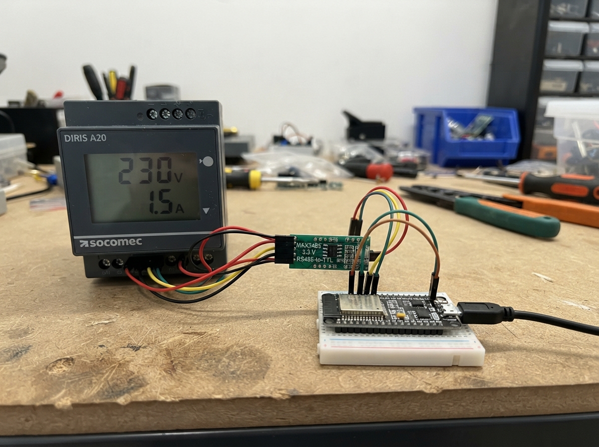
This project builds a real-time power monitor using an ESP32 microcontroller to read three-phase electrical measurements from a Socomec DIRIS A20 power meter. The ESP32 communicates with the meter over RS485 using Modbus protocol, then publishes voltage, current, and power data to an MQTT broker for remote monitoring and logging.
The guide provides a complete wiring diagram showing how to connect the MAX3485 RS485-to-TTL converter between the ESP32 and the DIRIS A20 meter, a full parts list, ready-to-deploy firmware with WiFi and MQTT integration, and step-by-step assembly instructions. Builders will have everything needed to monitor three-phase power consumption across a home or facility.
Wiring diagram

Gather all the parts
Assemble it in 6 steps
1. Turn off the meter and ESP32
Switch off the DIRIS A20 supply and unplug the ESP32 USB cable before touching the communication terminals. The meter may be installed near hazardous mains wiring, so only work on its low-voltage RS485 terminals after the installation is safe.
- Do not connect the ESP32 or converter to any mains voltage terminal; this project uses only the meter's RS485 communication terminals.
2. Connect the ESP32 to the RS485 converter
Use the 3.3 V pin on the ESP32, not its 5 V/VIN pin. Connect MAX3485 VCC to ESP32 3V3 (power), MAX3485 GND to ESP32 GND (ground), MAX3485 RO to GPIO16 (data received from the meter), and MAX3485 DI to GPIO17 (data sent to the meter).
- GPIO16 and GPIO17 are printed on the ESP32 board. They are separate from the USB serial pins, so Deploy and meter communication can work together.
- Make sure VCC and GND are not swapped — swapped power can damage the converter.
3. Connect the two direction-control wires
Connect MAX3485 DE to ESP32 GPIO25 (it turns on sending), then connect MAX3485 RE to ESP32 GPIO26 (it turns on listening). Keep DE and RE as two separate wires because this converter board exposes them separately.
- These wires let the ESP32 take turns talking and listening on the shared meter cable.
4. Connect the meter communication pair
Connect DIRIS A20 A(+) to MAX3485 A (RS485 data), and connect DIRIS A20 B(-) to MAX3485 B (RS485 data). If the DIRIS has a terminal specifically labelled RS485 GND or COM GND, connect it to MAX3485 GND (shared reference).
- Use a twisted pair for A and B, especially for a long cable. Keep the pair away from mains cables where possible.
- Do not connect the DIRIS A(+) or B(-) wires to ESP32 GPIO1 or GPIO2; they must go to the converter's A and B screw terminals. If readings fail, first check that A and B have not been swapped.
5. Add termination only when needed
For a long cable run or a cable with a converter at each end, place one 120 ohm resistor across MAX3485 A and B at the end of the cable. Leave it out for a short, single-meter lead unless the meter manual or the existing network requires it.
- There should normally be only two terminating resistors on one long RS485 cable: one at each physical end.
- Do not put a resistor from A or B to 3V3, 5V, or GND; the 120 ohm resistor goes only between A and B.
6. Power up and deploy
Inspect every wire, plug the ESP32 into USB, then restore the meter supply. In Schematik, press Deploy to compile and flash the firmware. The ESP32 joins the DIRIS_MONITOR Wi-Fi network and sends readings to the configured MQTT server.
- Grafana normally reads these values through an MQTT-to-database flow. Subscribe to diris_a20/telemetry to confirm the JSON messages first.
Review all connections
1. Connections between "rs485_3v3" and "ESP32"
2. Connections between "diris_a20" and "ESP32"
Deploy the firmware
#include <Arduino.h>
#include <WiFi.h>
#include <PubSubClient.h>
#include <ModbusMaster.h>

// Network and MQTT settings supplied for this installation.

// Forward declarations
void beforeModbusTransmission();
void afterModbusTransmission();
bool readFloatInput(uint16_t oneBasedRegister, float &value);
void publishText(const char* topic, const char* payload, bool retained);
void ensureWiFi();
void ensureMqtt();
void pollAndPublish();

const char* WIFI_SSID = "DIRIS_MONITOR";
const char* WIFI_PASSWORD = "JUSTMONITOR";
const char* MQTT_HOST = "192.168.100.101";
const uint16_t MQTT_PORT = 8106;
const char* MQTT_USER = "root";
const char* MQTT_PASSWORD = "gadamonTE";

// ESP32 UART2 to the 3.3 V MAX3485 module.
const int RS485_RX_PIN = 16;  // MAX3485 RO
const int RS485_TX_PIN = 17;  // MAX3485 DI
const int RS485_DE_PIN = 25;  // MAX3485 DE, HIGH while transmitting
const int RS485_RE_PIN = 26;  // MAX3485 RE, LOW enables the receiver
const uint8_t DIRIS_SLAVE_ID = 1;
const uint32_t DIRIS_BAUD = 19200;

// DIRIS A20 measurement table: these are one-based Modbus input-register
// numbers. ModbusMaster uses zero-based addresses, hence the -1 below.
const uint16_t REG_VOLTAGE_L1 = 50514;
const uint16_t REG_VOLTAGE_L2 = 50516;
const uint16_t REG_VOLTAGE_L3 = 50518;
const uint16_t REG_CURRENT_L1 = 50520;
const uint16_t REG_CURRENT_L2 = 50522;
const uint16_t REG_CURRENT_L3 = 50524;
const uint16_t REG_ACTIVE_POWER_TOTAL = 50550;

HardwareSerial meterSerial(2);
ModbusMaster diris;
WiFiClient wifiClient;
PubSubClient mqtt(wifiClient);

unsigned long lastPollMs = 0;
unsigned long lastWiFiAttemptMs = 0;
unsigned long lastMqttAttemptMs = 0;
const unsigned long POLL_INTERVAL_MS = 5000;

void beforeModbusTransmission() {
  digitalWrite(RS485_RE_PIN, HIGH);  // turn off receiver while sending
  digitalWrite(RS485_DE_PIN, HIGH);  // enable RS485 driver
  delayMicroseconds(200);
}

void afterModbusTransmission() {
  meterSerial.flush();
  delayMicroseconds(200);
  digitalWrite(RS485_DE_PIN, LOW);  // release the shared RS485 pair
  digitalWrite(RS485_RE_PIN, LOW);  // listen for the meter reply
}

bool readFloatInput(uint16_t oneBasedRegister, float &value) {
  uint8_t result = diris.readInputRegisters(oneBasedRegister - 1, 2);
  if (result != diris.ku8MBSuccess) {
    Serial.printf("Modbus read %u failed: 0x%02X\n", oneBasedRegister, result);
    return false;
  }

  // DIRIS values are IEEE-754 float32 values, high 16-bit word first.
  uint32_t raw = (static_cast<uint32_t>(diris.getResponseBuffer(0)) << 16) |
                 diris.getResponseBuffer(1);
  memcpy(&value, &raw, sizeof(value));
  return isfinite(value);
}

void publishText(const char* topic, const char* payload, bool retained = false) {
  if (mqtt.connected()) {
    mqtt.publish(topic, payload, retained);
  }
}

void ensureWiFi() {
  if (WiFi.status() == WL_CONNECTED) return;
  if (millis() - lastWiFiAttemptMs < 10000) return;

  lastWiFiAttemptMs = millis();
  Serial.printf("Connecting to Wi-Fi %s\n", WIFI_SSID);
  WiFi.disconnect();
  WiFi.begin(WIFI_SSID, WIFI_PASSWORD);
}

void ensureMqtt() {
  if (WiFi.status() != WL_CONNECTED || mqtt.connected()) return;
  if (millis() - lastMqttAttemptMs < 5000) return;

  lastMqttAttemptMs = millis();
  String clientId = "diris-a20-" + String(static_cast<uint32_t>(ESP.getEfuseMac()), HEX);
  if (mqtt.connect(clientId.c_str(), MQTT_USER, MQTT_PASSWORD,
                   "diris_a20/status", 0, true, "offline")) {
    publishText("diris_a20/status", "online", true);
    Serial.println("MQTT connected");
  } else {
    Serial.printf("MQTT connection failed, state %d\n", mqtt.state());
  }
}

void pollAndPublish() {
  float v1, v2, v3, i1, i2, i3, power;
  bool ok = readFloatInput(REG_VOLTAGE_L1, v1) &&
            readFloatInput(REG_VOLTAGE_L2, v2) &&
            readFloatInput(REG_VOLTAGE_L3, v3) &&
            readFloatInput(REG_CURRENT_L1, i1) &&
            readFloatInput(REG_CURRENT_L2, i2) &&
            readFloatInput(REG_CURRENT_L3, i3) &&
            readFloatInput(REG_ACTIVE_POWER_TOTAL, power);

  if (!ok) {
    publishText("diris_a20/status", "modbus_read_error", true);
    return;
  }

  char payload[256];
  snprintf(payload, sizeof(payload),
           "{\"voltage_l1_v\":%.2f,\"voltage_l2_v\":%.2f,\"voltage_l3_v\":%.2f,"
           "\"current_l1_a\":%.3f,\"current_l2_a\":%.3f,\"current_l3_a\":%.3f,"
           "\"active_power_total_w\":%.2f}",
           v1, v2, v3, i1, i2, i3, power);
  publishText("diris_a20/telemetry", payload);
  publishText("diris_a20/status", "online", true);
  Serial.printf("Published: %s\n", payload);
}

void setup() {
  Serial.begin(115200);
  pinMode(RS485_DE_PIN, OUTPUT);
  pinMode(RS485_RE_PIN, OUTPUT);
  digitalWrite(RS485_DE_PIN, LOW);
  digitalWrite(RS485_RE_PIN, LOW);

  meterSerial.begin(DIRIS_BAUD, SERIAL_8N1, RS485_RX_PIN, RS485_TX_PIN);
  diris.begin(DIRIS_SLAVE_ID, meterSerial);
  diris.preTransmission(beforeModbusTransmission);
  diris.postTransmission(afterModbusTransmission);

  WiFi.mode(WIFI_STA);
  mqtt.setServer(MQTT_HOST, MQTT_PORT);
  ensureWiFi();
}

void loop() {
  ensureWiFi();
  ensureMqtt();
  if (mqtt.connected()) mqtt.loop();

  if (millis() - lastPollMs >= POLL_INTERVAL_MS) {
    lastPollMs = millis();
    if (mqtt.connected()) pollAndPublish();
  }
}
Remix this project
Make it yours in one click
Open a full copy of this project in your own Schematik workspace — diagram, code, parts, and assembly steps included. Swap the sensor, add features, or redesign the whole thing with AI. The author's original stays untouched.