Community project
ESP32 Remote-Controlled Car
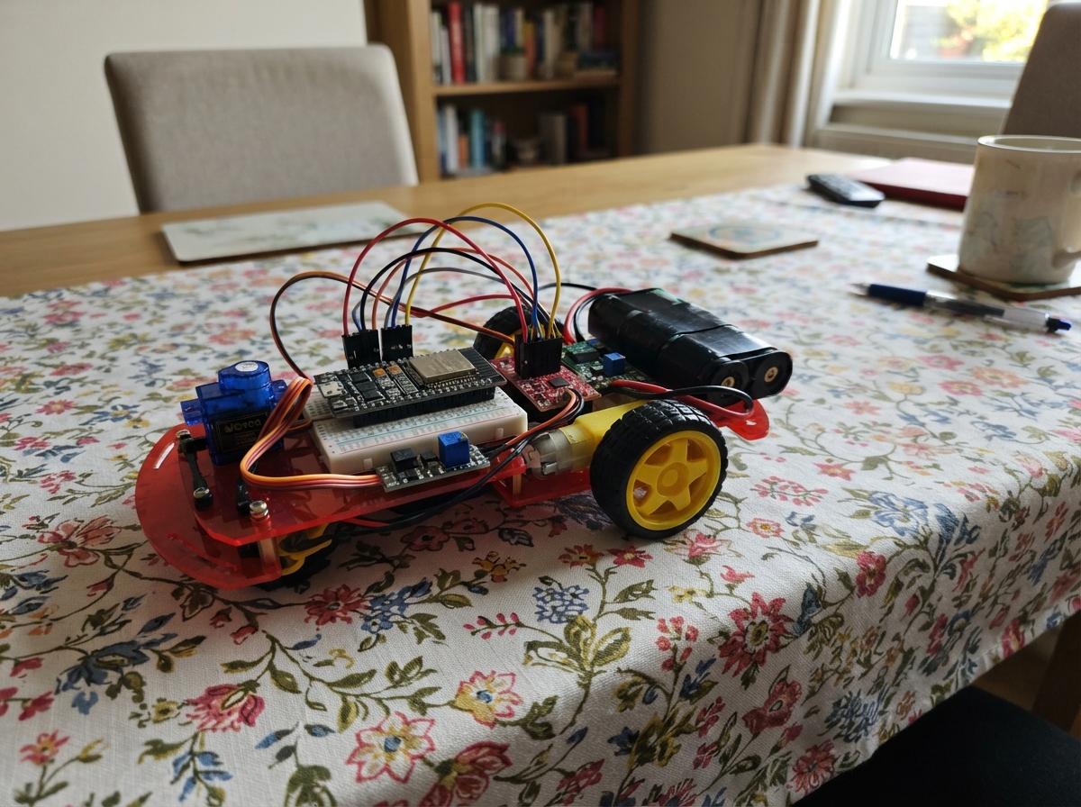
Build a WiFi-controlled car powered by an ESP32 that streams live video and responds to remote commands over the network. This project combines a 7.4V lithium battery system with regulated power delivery, dual-motor control via the TB6612FNG driver, and precise steering through an MG90S servo for a fully autonomous remote platform.
The guide provides a complete wiring diagram, detailed parts list, and step-by-step assembly instructions with critical setup procedures for the buck converters and battery management system. Firmware code enables WiFi access-point mode, HTTP server control, camera streaming, and motor/servo coordination—everything needed to drive and steer the car from a web interface while viewing the onboard camera feed.
Wiring diagram

Gather all the parts
Assemble it in 6 steps
1. Connect the two cells and the BMS
Use only a 2S battery holder or pack that brings out three battery wires. Connect battery_1 BAT- to bms_1 B- (cell 1 negative), battery_1 BM to bms_1 BM (the join between the two cells), and battery_1 BAT+ to bms_1 B+ (cell 2 positive). The on/off switch built into your battery box stays in use; do not add another switch.
- On your HX-2S board, BM is the small pad on the right side between B+ and B−.
- Use appropriately sized wire for these battery connections because they carry the combined load current.
- A fully charged two-cell pack is about 8.4 V. Reversing B+ and B−, or leaving BM disconnected, can damage the BMS or leave one cell unprotected.
- If your battery holder has only two wires and no midpoint wire, do not use it with this BMS until you replace it with a 2S holder/pack that exposes B−, BM, and B+.
2. Set both buck converters before connecting the car
Connect bms_1 P+ to the VIN pin of buck_1 and buck_motor_6v_1 (protected battery input power). Connect bms_1 P- to the GND pin of both converters (ground). With the motor, servo, and ESP32 disconnected, use a multimeter to adjust buck_1 to exactly 5.0 V and buck_motor_6v_1 to exactly 6.0 V.
- Label the 5 V output wire and 6 V output wire so they cannot be mixed up.
- Recheck each voltage after tightening the adjustment screw.
- Do not connect the 6 V buck output to the ESP32 or servo; 6 V can damage the ESP32 board.
- Do not connect the raw 8.4 V battery output to the servo, ESP32, or 6 V motor.
3. Connect the 5 V buck directly to the servo and ESP32
Make two separate branches from buck_1 VOUT: one wire goes directly to servo_1 VCC, the red wire (5 V power), and a second wire goes directly to the Freenove ESP32-S3 camera board 5V/VIN pin (5 V power). Connect servo_1 GND, the brown or black wire, directly to buck_1 GND (ground). Connect buck_1 GND to an ESP32 GND pin (ground). The servo is powered straight from the 5 V buck, not through the ESP32.
- The saved schematic edge is servo_1 GND directly to buck_1 GND; place the brown/black servo wire in the 5 V converter ground terminal area.
- Keep power wires short and secure.
- Make sure the servo’s red and brown/black wires are not swapped — swapped power can damage the servo.
- Do not connect buck_1 VOUT to either converter VIN pin; that would short the regulated output into the battery-input side.
- Set the buck to 5.0 V before plugging it into the ESP32.
4. Wire the regulated motor supply and driver
Connect buck_motor_6v_1 VOUT to motor_driver_1 VM (regulated 6 V motor power). Connect buck_motor_6v_1 GND to the shared BMS P− ground (ground). Connect motor_driver_1 GND to that same shared ground (ground). Connect motor_driver_1 VCC to the ESP32 3V3 pin (logic power). Add a short direct wire from motor_driver_1 STBY to motor_driver_1 VCC (permanent 3.3 V enable). Connect A01 to motor_1 M+ and A02 to motor_1 M− (motor outputs). Connect AIN1 to GPIO1 (direction signal), AIN2 to GPIO2 (direction signal), and PWMA to GPIO14 (speed signal). Leave GPIO3 unconnected.
- If Forward turns the wheel backward, swap the motor wires at A01 and A02.
- Keep motor wires away from the camera antenna and small signal wires.
- The STBY-to-VCC wire is on the TB6612 module itself; it is not an ESP32 GPIO connection.
- Do not connect TB6612 VM to the raw battery; it must receive the regulated 6.0 V output.
- Never connect the motor directly to an ESP32 pin — motor current can damage the board.
- Do not connect STBY to GPIO3 or any other ESP32 pin; STBY must remain directly tied to the driver VCC pin.
5. Connect the steering signal without using GPIO38
Connect ESP32 GPIO21 directly to servo_1 SIG, the orange or yellow wire (steering signal). The servo receives its 5 V power directly from buck_1 VOUT; the ESP32 sends only the steering signal. Leave GPIO38 unconnected.
- Keep this signal wire short and secure so vibration does not make steering glitch.
- All grounds — BMS P−, both bucks, ESP32, TB6612, and servo — must join together.
- Do not connect the servo signal wire to a 5 V power wire; that can damage the ESP32 pin.
- If steering jitters or does not move, stop and check the shared ground first.
6. Test slow and fast safely
Lift the driven wheel off the table. Turn on the switch built into the battery box so power reaches the protected BMS output. Join your phone to Wi-Fi RC-CAR-CAM using password drivecar, then open http://192.168.4.1. Choose Slow or Fast, then hold Forward or Reverse; releasing the button stops the motor. Fast uses about 71% PWM and Slow uses about 41% PWM into the regulated 6.0 V motor supply.
- Start with Slow to confirm wheel direction and steering.
- Use Centre steering before driving.
- Keep fingers, hair, and loose wires away from the wheel and steering linkage.
- Disconnect the battery at once if you smell hot plastic, see smoke, or feel a wire getting hot.
Review all connections
1. Connections between "battery_1" and "ESP32"
2. Connections between "bms_1" and "ESP32"
3. Connections between "buck_1" and "ESP32"
4. Connections between "servo_1" and "ESP32"
5. Connections between "buck_motor_6v_1" and "ESP32"
6. Connections between "motor_driver_1" and "ESP32"
Deploy the firmware
#include <Arduino.h> // Arduino GPIO and timing support. // פונקציות GPIO וזמן של Arduino.
#include <WiFi.h> // ESP32 Wi-Fi access-point support. // תמיכה ברשת Wi‑Fi של ESP32.
#include <ESP32Servo.h> // MG90S steering control. // שליטה בסרוו ההיגוי.
#include "esp_camera.h" // ESP32 camera driver. // מנהל המצלמה של ESP32.
#include "esp_http_server.h" // ESP-IDF HTTP server. // שרת האינטרנט המובנה.

// Freenove ESP32-S3-WROOM camera-board OV2640 factory wiring. // מיפוי המצלמה המובנה בלוח Freenove.
#define PWDN_GPIO_NUM    -1
#define RESET_GPIO_NUM   -1
#define XCLK_GPIO_NUM    15
#define SIOD_GPIO_NUM     4
#define SIOC_GPIO_NUM     5
#define Y9_GPIO_NUM      16
#define Y8_GPIO_NUM      17
#define Y7_GPIO_NUM      18
#define Y6_GPIO_NUM      12
#define Y5_GPIO_NUM      10
#define Y4_GPIO_NUM       8
#define Y3_GPIO_NUM       9
#define Y2_GPIO_NUM      11
#define VSYNC_GPIO_NUM    6
#define HREF_GPIO_NUM     7
#define PCLK_GPIO_NUM    13

// Forward declarations
void stopMotor();
void driveMotor(bool forward);
esp_err_t indexHandler(httpd_req_t *request);
esp_err_t controlHandler(httpd_req_t *request);
esp_err_t streamHandler(httpd_req_t *request);
bool startCamera();
bool startServer(httpd_handle_t *server, uint16_t port, const httpd_uri_t *uris, size_t uriCount);
bool startWebServers();

const int MOTOR_AIN1_PIN = 1; // TB6612 AIN1 direction input. // כניסת כיוון AIN1 של TB6612.
const int MOTOR_AIN2_PIN = 2; // TB6612 AIN2 direction input. // כניסת כיוון AIN2 של TB6612.
const int MOTOR_PWMA_PIN = 14; // TB6612 PWMA speed input. // כניסת מהירות PWMA של TB6612.
const uint8_t MOTOR_LEDC_CHANNEL = 2; // Explicit Arduino LEDC channel for the 20 kHz motor PWM output. // ערוץ LEDC מפורש של Arduino עבור PWM המנוע בתדר 20 קה"ץ.
const int SERVO_PIN = 21; // The physical MG90S signal wire is GPIO21. // חוט אות הסרוו מחובר פיזית ל־GPIO21.

const char *AP_NAME = "RC-CAR-CAM";
const char *AP_PASSWORD = "drivecar";
const uint16_t CONTROL_SERVER_PORT = 80;
const uint16_t STREAM_SERVER_PORT = 81; // Separate server keeps the continuous stream from blocking control requests. // שרת נפרד מונע מהווידאו לחסום פקודות.

// These are PWM duty counts on the regulated 6.0 V motor rail. // ערכי PWM על אספקת מנוע מווסתת של 6 וולט.
const uint8_t DRIVE_POWER_SLOW = 105; // 41.2% duty; approximately 2.47 V average-equivalent. // מהירות איטית.
const uint8_t DRIVE_POWER_FAST = 180; // 70.6% duty; approximately 4.24 V average-equivalent. // מהירות מהירה.
const int STEER_LEFT = 55;
const int STEER_CENTRE = 90;
const int STEER_RIGHT = 125;
const unsigned long COMMAND_TIMEOUT_MS = 700; // Held drive commands arrive every 200 ms. // פקודות נסיעה מוחזקות מגיעות כל 200 אלפיות שנייה.

Servo steering;
httpd_handle_t controlServer = nullptr;
httpd_handle_t streamServer = nullptr;
volatile unsigned long lastDriveCommandMs = 0; // Shared with the HTTP-server task. // משותף עם משימת שרת האינטרנט.
volatile uint8_t selectedDrivePower = DRIVE_POWER_SLOW;

void stopMotor() {
  ledcWrite(MOTOR_PWMA_PIN, 0); // Remove PWM first. // קודם מבטל PWM.
  digitalWrite(MOTOR_AIN1_PIN, LOW);
  digitalWrite(MOTOR_AIN2_PIN, LOW); // IN1=0, IN2=0, PWM=0 is TB6612 stop/coast. // זהו מצב עצירה חופשית של TB6612.
}

void driveMotor(bool forward) {
  digitalWrite(MOTOR_AIN1_PIN, forward ? HIGH : LOW);
  digitalWrite(MOTOR_AIN2_PIN, forward ? LOW : HIGH);
  ledcWrite(MOTOR_PWMA_PIN, selectedDrivePower);
  lastDriveCommandMs = millis();
}

const char INDEX_HTML[] PROGMEM = R"HTML(
<!doctype html><html><head><meta name="viewport" content="width=device-width,initial-scale=1"><title>RC Car Camera</title><style>body{margin:0;background:#15191f;color:#fff;font:18px Arial;text-align:center}h2{margin:14px}img{width:min(100%,640px);background:#000}.grid{display:grid;grid-template-columns:repeat(3,96px);gap:10px;justify-content:center;margin:16px}button{height:58px;border:0;border-radius:12px;background:#2684ff;color:#fff;font-size:17px;font-weight:bold}.stop{background:#e5484d}.note{font-size:13px;color:#b9c4d0;margin:8px 18px 20px}</style></head><body><h2>RC Car Camera</h2><img id="stream" alt="Camera stream"><div class="grid"><div></div><button id="forward">Forward</button><div></div><button onclick="go('left')">Left</button><button class="stop" onclick="go('stop')">Stop</button><button onclick="go('right')">Right</button><div></div><button id="reverse">Reverse</button><div></div><button onclick="go('centre')">Centre steering</button></div><p><button id="slow" onclick="speed('slow')">Slow</button> <button id="fast" onclick="speed('fast')">Fast</button></p><p class="note">Choose a speed, then hold Forward or Reverse to drive. Releasing the button stops the motor.</p><script>document.getElementById('stream').src='http://'+location.hostname+':81/stream';function go(c){fetch('/control?cmd='+c).catch(()=>{});}function speed(s){go(s);document.getElementById('slow').style.background=s==='slow'?'#26a269':'#2684ff';document.getElementById('fast').style.background=s==='fast'?'#26a269':'#2684ff';}function hold(id,cmd){let t=null;const b=document.getElementById(id);const start=e=>{e.preventDefault();if(t!==null)clearInterval(t);go(cmd);t=setInterval(()=>go(cmd),200);};const end=e=>{e.preventDefault();if(t!==null){clearInterval(t);t=null;}go('stop');};b.addEventListener('pointerdown',start);b.addEventListener('pointerup',end);b.addEventListener('pointerleave',end);b.addEventListener('pointercancel',end);}speed('slow');hold('forward','forward');hold('reverse','reverse');</script></body></html>
)HTML";

esp_err_t indexHandler(httpd_req_t *request) {
  httpd_resp_set_type(request, "text/html");
  return httpd_resp_send(request, INDEX_HTML, HTTPD_RESP_USE_STRLEN);
}

esp_err_t controlHandler(httpd_req_t *request) {
  char query[64] = {0};
  char command[16] = {0};
  if (httpd_req_get_url_query_str(request, query, sizeof(query)) != ESP_OK || httpd_query_key_value(query, "cmd", command, sizeof(command)) != ESP_OK) {
    httpd_resp_send_err(request, HTTPD_400_BAD_REQUEST, "Missing cmd");
    return ESP_FAIL;
  }
  if (strcmp(command, "forward") == 0) driveMotor(true);
  else if (strcmp(command, "reverse") == 0) driveMotor(false);
  else if (strcmp(command, "stop") == 0) { stopMotor(); lastDriveCommandMs = 0; }
  else if (strcmp(command, "slow") == 0) selectedDrivePower = DRIVE_POWER_SLOW;
  else if (strcmp(command, "fast") == 0) selectedDrivePower = DRIVE_POWER_FAST;
  else if (strcmp(command, "left") == 0) steering.write(STEER_LEFT);
  else if (strcmp(command, "right") == 0) steering.write(STEER_RIGHT);
  else if (strcmp(command, "centre") == 0) steering.write(STEER_CENTRE);
  else { httpd_resp_send_err(request, HTTPD_400_BAD_REQUEST, "Unknown cmd"); return ESP_FAIL; }
  httpd_resp_set_type(request, "text/plain");
  return httpd_resp_sendstr(request, "OK");
}

esp_err_t streamHandler(httpd_req_t *request) {
  static const char *CONTENT_TYPE = "multipart/x-mixed-replace;boundary=frame";
  static const char *BOUNDARY = "\r\n--frame\r\n";
  char header[64];
  httpd_resp_set_type(request, CONTENT_TYPE);
  while (true) {
    camera_fb_t *frame = esp_camera_fb_get();
    if (frame == nullptr) return ESP_FAIL;
    esp_err_t result = httpd_resp_send_chunk(request, BOUNDARY, strlen(BOUNDARY));
    if (result == ESP_OK) {
      int length = snprintf(header, sizeof(header), "Content-Type: image/jpeg\r\nContent-Length: %u\r\n\r\n", static_cast<unsigned>(frame->len));
      result = httpd_resp_send_chunk(request, header, length);
    }
    if (result == ESP_OK) result = httpd_resp_send_chunk(request, reinterpret_cast<const char *>(frame->buf), frame->len);
    esp_camera_fb_return(frame); // Always return the acquired frame before leaving. // תמיד מחזיר את מאגר התמונה.
    if (result != ESP_OK) return result;
  }
}

bool startCamera() {
  camera_config_t config = {};
  config.ledc_channel = LEDC_CHANNEL_0; // Camera-driver XCLK configuration for this ESP32-S3 board. // הגדרת שעון XCLK של מנהל המצלמה עבור לוח ESP32-S3 זה.
  config.ledc_timer = LEDC_TIMER_0;
  config.pin_d0 = Y2_GPIO_NUM; config.pin_d1 = Y3_GPIO_NUM; config.pin_d2 = Y4_GPIO_NUM; config.pin_d3 = Y5_GPIO_NUM;
  config.pin_d4 = Y6_GPIO_NUM; config.pin_d5 = Y7_GPIO_NUM; config.pin_d6 = Y8_GPIO_NUM; config.pin_d7 = Y9_GPIO_NUM;
  config.pin_xclk = XCLK_GPIO_NUM; config.pin_pclk = PCLK_GPIO_NUM; config.pin_vsync = VSYNC_GPIO_NUM; config.pin_href = HREF_GPIO_NUM;
  config.pin_sccb_sda = SIOD_GPIO_NUM; config.pin_sccb_scl = SIOC_GPIO_NUM; config.pin_pwdn = PWDN_GPIO_NUM; config.pin_reset = RESET_GPIO_NUM;
  config.xclk_freq_hz = 20000000;
  config.pixel_format = PIXFORMAT_JPEG;
  config.frame_size = FRAMESIZE_QVGA;
  config.jpeg_quality = 12;
  config.fb_count = 2;
  config.fb_location = CAMERA_FB_IN_PSRAM;
  config.grab_mode = CAMERA_GRAB_LATEST;
  esp_err_t result = esp_camera_init(&config);
  if (result != ESP_OK) Serial.printf("Camera initialization failed: 0x%x\n", result);
  return result == ESP_OK;
}

bool startServer(httpd_handle_t *server, uint16_t port, const httpd_uri_t *uris, size_t uriCount) {
  httpd_config_t config = HTTPD_DEFAULT_CONFIG();
  config.server_port = port;
  config.ctrl_port = static_cast<uint16_t>(config.ctrl_port + (port - CONTROL_SERVER_PORT)); // Each server has its own internal control port. // לכל שרת יש פורט בקרה פנימי נפרד.
  config.lru_purge_enable = true;
  if (httpd_start(server, &config) != ESP_OK) return false;
  for (size_t i = 0; i < uriCount; ++i) {
    if (httpd_register_uri_handler(*server, &uris[i]) != ESP_OK) { httpd_stop(*server); *server = nullptr; return false; }
  }
  return true;
}

bool startWebServers() {
  httpd_uri_t indexUri = {}; indexUri.uri = "/"; indexUri.method = HTTP_GET; indexUri.handler = indexHandler;
  httpd_uri_t controlUri = {}; controlUri.uri = "/control"; controlUri.method = HTTP_GET; controlUri.handler = controlHandler;
  httpd_uri_t streamUri = {}; streamUri.uri = "/stream"; streamUri.method = HTTP_GET; streamUri.handler = streamHandler;
  const httpd_uri_t controlUris[] = {indexUri, controlUri};
  const httpd_uri_t streamUris[] = {streamUri};
  if (!startServer(&controlServer, CONTROL_SERVER_PORT, controlUris, 2)) return false;
  if (!startServer(&streamServer, STREAM_SERVER_PORT, streamUris, 1)) { httpd_stop(controlServer); controlServer = nullptr; return false; }
  return true;
}

void setup() {
  Serial.begin(115200);
  pinMode(MOTOR_AIN1_PIN, OUTPUT); pinMode(MOTOR_AIN2_PIN, OUTPUT);
  digitalWrite(MOTOR_AIN1_PIN, LOW); digitalWrite(MOTOR_AIN2_PIN, LOW); // Keep the TB6612 direction inputs inactive while peripherals start. // שומר את כניסות הכיוון של TB6612 לא פעילות בזמן האתחול.
  if (!startCamera()) return; // Start the OV2640 camera using its board-specific camera-driver configuration. // מפעיל את מצלמת OV2640 לפי הגדרת מנהל המצלמה של הלוח.
  if (!ledcAttachChannel(MOTOR_PWMA_PIN, 20000, 8, MOTOR_LEDC_CHANNEL)) { Serial.println("Motor PWM setup failed"); return; }
  stopMotor();
  steering.setPeriodHertz(50);
  if (!steering.attach(SERVO_PIN, 500, 2400)) { Serial.println("Servo setup failed"); return; }
  steering.write(STEER_CENTRE);
  WiFi.mode(WIFI_AP);
  if (!WiFi.softAP(AP_NAME, AP_PASSWORD)) { Serial.println("Wi-Fi access point failed"); return; }
  Serial.print("Control page: http://"); Serial.println(WiFi.softAPIP());
  if (!startWebServers()) Serial.println("HTTP server startup failed");
}

void loop() {
  unsigned long lastCommand = lastDriveCommandMs;
  if (lastCommand != 0 && millis() - lastCommand > COMMAND_TIMEOUT_MS) { stopMotor(); lastDriveCommandMs = 0; }
  delay(10);
}
Remix this project
Make it yours in one click
Open a full copy of this project in your own Schematik workspace — diagram, code, parts, and assembly steps included. Swap the sensor, add features, or redesign the whole thing with AI. The author's original stays untouched.