Community project
Footstep Force Measurement
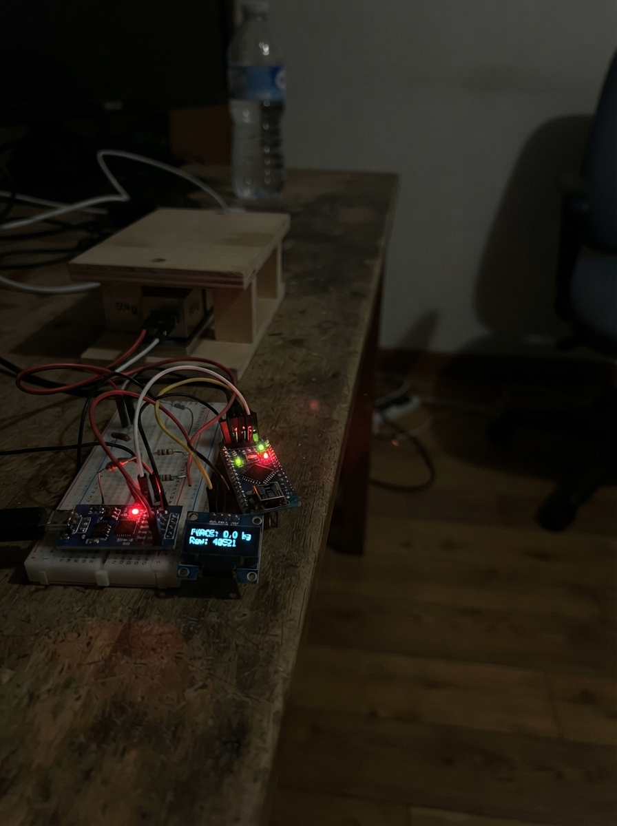
This project measures the force exerted by footsteps using a load cell sensor platform. The system captures weight data through a 50 kg load cell connected to an HX711 amplifier, which converts analog signals into digital readings that the Arduino processes and outputs via serial communication.
The guide provides a complete parts list, wiring diagram, and step-by-step assembly instructions for building a rigid sensor platform and connecting the electronics. Included firmware handles calibration and real-time weight measurement, allowing makers to log footstep force data for biomechanics analysis, fitness tracking, or interactive installations.
Wiring diagram

Gather all the parts
Assemble it in 6 steps
1. Build a stiff platform over the four sensors
Put load_cell_1, load_cell_2, load_cell_3, and load_cell_4 under the four corners of a rigid top plate. Keep every sensor's arrow or marked loading direction facing the same way, and arrange them in order around the platform: 1 front-left, 2 front-right, 3 rear-right, 4 rear-left. Fasten the fixed end of each sensor to the base and let only its loading end support the top plate so the metal can bend slightly.
- Leave enough clearance that the top plate cannot touch the base anywhere except through the four sensors.
- The four 50 kg cells give a platform rating of roughly 200 kg only when the weight is shared evenly; use a safety margin.
- Do not jump onto the platform or exceed the mechanical rating — a sudden impact can permanently bend a sensor or make the platform unstable.
2. Check each sensor wire before joining it
With the platform unplugged, use a multimeter on resistance mode for each load cell. Find the two wires with the largest resistance; these are the outer wires. The remaining wire is the centre wire. This design calls those wires BLACK and WHITE for the outer pair and RED for the centre wire, but label the actual wires you find because colours can differ between batches.
- A typical cell measures about twice as much resistance between its two outer wires as from the centre wire to either outer wire.
- Use small labels such as 1R, 1B, and 1W before soldering so the four corners do not get mixed up.
- Do not rely on wire colours alone — joining the wrong wires prevents correct measurement and can make the reading move in the wrong direction.
3. Join the four outer sensor wires into a ring
Make four insulated joins: load_cell_1 BLACK to load_cell_2 BLACK; load_cell_2 WHITE to load_cell_3 WHITE; load_cell_3 BLACK to load_cell_4 BLACK; and load_cell_4 WHITE to load_cell_1 WHITE. These four joins make the outside loop of the measuring bridge.
- Twist, solder, and cover each join with heat-shrink tubing; keep the cable away from moving or flexing parts of the platform.
- Keep the cells in the front-left, front-right, rear-right, rear-left order while making these joins.
- Bare wire joins can touch each other and stop the platform from measuring correctly, so cover every join separately.
4. Connect the four centre sensor wires to the HX711
Connect load_cell_1 RED to hx711_1 E+ (bridge power positive); load_cell_3 RED to hx711_1 E- (bridge power negative); load_cell_2 RED to hx711_1 A+ (measurement positive); and load_cell_4 RED to hx711_1 A- (measurement negative).
- Use the HX711 terminals marked E+, E-, A+, and A-; leave B+ and B- unused.
- If weight makes the final number negative after calibration, use the opposite sign for CALIBRATION_FACTOR rather than moving the bridge wires.
- Do not connect any load-cell wire to the HX711 B+ or B- terminals — this design reads the A channel only.
5. Wire the HX711 to the Arduino Mega
Connect hx711_1 VCC to the Mega 5V pin (power); hx711_1 GND to a Mega GND pin (ground); hx711_1 DT to Mega D2 (data); and hx711_1 SCK to Mega D3 (clock).
- Keep the four load-cell leads and HX711 close together and away from USB power leads where possible.
- The Mega's USB cable powers this low-current circuit.
- Make sure 5V and GND are not swapped — swapped power can damage the HX711 module.
6. Protect the electronics and set the zero reading
Put the HX711 and Arduino where feet cannot strike them, then plug the Mega into USB with the platform empty and still. The sketch sets that unloaded condition as zero during startup. To make kilograms accurate, replace CALIBRATION_FACTOR in the code with the value measured using a known mass placed near the platform centre.
- Use a known mass that is large enough to give a stable change, then repeat the check near each corner.
- The Serial output is one bare number every 50 milliseconds, ready for a plot or data capture.
- Do not put weight on the platform while it starts, or that weight becomes part of the zero reference until the board is restarted.
Review all connections
1. Connections between "hx711_1" and "Arduino"
2. Connections between "load_cell_1" and "Arduino"
3. Connections between "load_cell_2" and "Arduino"
4. Connections between "load_cell_3" and "Arduino"
5. Connections between "load_cell_4" and "Arduino"
Deploy the firmware
#include <Arduino.h>
#include <HX711.h>

const uint8_t HX711_DOUT_PIN = 2;
const uint8_t HX711_SCK_PIN = 3;

// Replace this with the factor measured using a known reference mass.
const float CALIBRATION_FACTOR = -7050.0f;

HX711 scale;

void setup() {
  Serial.begin(115200);

  scale.begin(HX711_DOUT_PIN, HX711_SCK_PIN);
  scale.set_scale(CALIBRATION_FACTOR);
  scale.tare();
}

void loop() {
  if (scale.is_ready()) {
    const float weightKg = scale.get_units(1);
    Serial.println(weightKg, 3);
  }

  delay(50);
}
Remix this project
Make it yours in one click
Open a full copy of this project in your own Schematik workspace — diagram, code, parts, and assembly steps included. Swap the sensor, add features, or redesign the whole thing with AI. The author's original stays untouched.