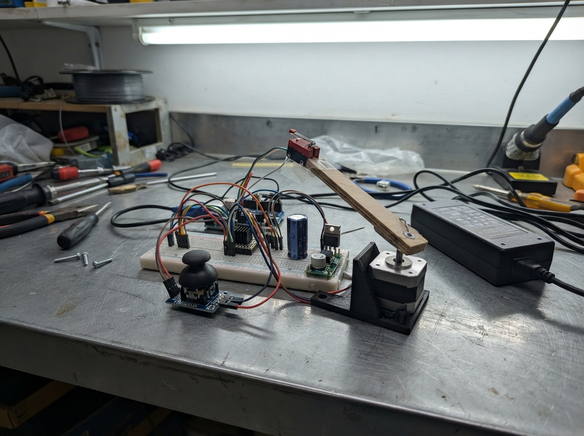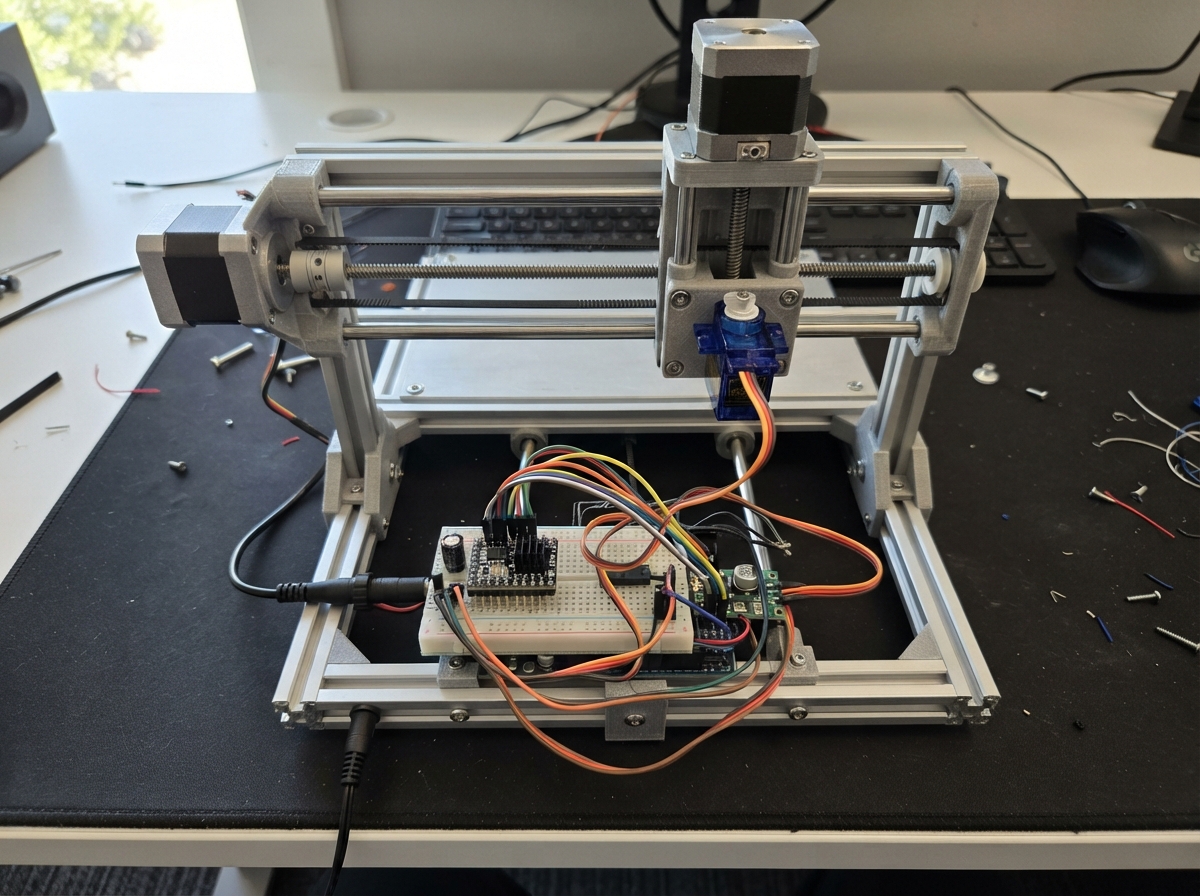
This guide builds a simple XY plotter capable of drawing designs on paper using an Arduino Uno and stepper motors. The machine uses two NEMA 17 stepper motors driven by A4988 carriers to move the drawing head across X and Y axes, while an SG90 servo lifts and lowers the pen between strokes.
The guide provides a complete wiring diagram, parts list, and Arduino firmware that accepts movement commands to draw patterns and images. Assembly covers mounting the motors, configuring the stepper drivers, wiring control signals, and running initial tests without ink to verify smooth operation across the full drawing area.
Wiring diagram
Gather all the parts
Assemble it in 7 steps
1. Préparer le châssis de dessin
Montez un petit châssis XY à courroies : deux rails linéaires, deux courroies GT2, deux poulies de 20 dents et un support de stylo. Fixez motor_x sur l’axe gauche-droite et motor_y sur l’axe avant-arrière. Fixez pen_servo au porte-stylo afin que son palonnier puisse lever le stylo sans le forcer.
- Un plateau d’environ 200 × 200 mm est une bonne taille de départ.
- Les courroies doivent être tendues comme une corde de guitare douce, sans être raides.
- N’utilisez pas de fraise, de moteur rapide ni de lame avec cette première version : elle est conçue pour déplacer un stylo seulement.
2. Régler les pilotes avant de les brancher
Avec l’alimentation débranchée, placez driver_x et driver_y sur un support isolant. Réglez chaque petite vis de courant très bas au départ ; elle limite la force qui chauffe les moteurs. Ne branchez jamais un moteur pendant qu’un pilote est alimenté.
- Un mauvais réglage de courant peut brûler un pilote ou rendre un moteur très chaud.
- Ne touchez pas les broches des A4988 lorsque le montage est sous tension.
3. Relier les moteurs aux pilotes
Pour motor_x, reliez les deux fils d’une même bobine aux bornes 1A et 1B de driver_x, puis les deux fils de l’autre bobine aux bornes 2A et 2B. Faites exactement la même chose entre motor_y et driver_y. Si un axe part dans le mauvais sens plus tard, inversez seulement les deux fils d’une bobine, alimentation retirée.
- Repérez d’abord les deux paires de fils de chaque moteur avec sa fiche technique ou un multimètre : une paire présente une petite résistance.
4. Câbler les signaux de commande
Reliez driver_x STEP à D2 (pas de l’axe X), driver_x DIR à D5 (sens de l’axe X), driver_y STEP à D3 (pas de l’axe Y) et driver_y DIR à D6 (sens de l’axe Y). Reliez EN de chaque pilote à GND (pilote actif), RST à SLP sur le même pilote (réveil), puis MS1, MS2 et MS3 à 5V (micro-pas). Reliez VDD de chaque pilote à 5V (alimentation logique) et GND_2 à GND (masse logique).
- Ne confondez pas VDD, l’alimentation logique 5 V, avec VMOT, l’alimentation moteur 12 V : les inverser peut détruire le pilote.
5. Ajouter les condensateurs et l’alimentation moteur
Placez cap_x directement entre VMOT et GND de driver_x : sa patte marquée + va sur VMOT (protection du 12 V) et sa bande – va sur GND (retour). Faites pareil avec cap_y et driver_y. Reliez le +12V de supply_12v aux deux VMOT, au VIN de buck_5v et au VIN de l’Arduino. Reliez tous les GND ensemble (masse commune).
- La bande sur un condensateur électrolytique indique le côté négatif ; l’inverser peut le faire chauffer ou éclater.
- Vérifiez au multimètre que l’adaptateur fournit bien 12 V continu avant de le connecter.
6. Alimenter et raccorder le lève-stylo
Avant de brancher pen_servo, réglez buck_5v à exactement 5,0 V avec un multimètre. Reliez sa sortie VOUT au fil rouge du servo (5 V), sa masse GND au fil brun ou noir (masse), et le fil orange ou jaune SIGNAL à D9 (ordre de lever ou poser le stylo).
- Ne branchez pas le servo au 12 V : cela l’endommagerait immédiatement.
- Assurez-vous que toutes les masses sont réunies, sinon les ordres envoyés au servo et aux pilotes seront instables.
7. Faire le premier test sans stylo
Débranchez d’abord l’alimentation 12 V, puis connectez l’Arduino par USB. Placez les axes au milieu de leur course à la main. Branchez ensuite le 12 V et observez que les moteurs restent seulement tièdes. Montez le stylo uniquement après avoir vérifié les déplacements sans charge.
- Le programme accepte par USB : G92 X0 Y0 pour définir le point de départ, M3 pour poser le stylo, M5 pour le lever, puis G0 X50 Y50 pour aller à 50 mm, 50 mm.
- Cette version n’a pas de capteurs de fin de course : ne commandez jamais un déplacement qui dépasse le châssis, car l’axe forcerait contre sa butée.
Review all connections
1. Connections between "supply_12v" and "Arduino"
2. Connections between "driver_x" and "Arduino"
3. Connections between "driver_y" and "Arduino"
4. Connections between "cap_x" and "Arduino"
5. Connections between "cap_y" and "Arduino"
6. Connections between "buck_5v" and "Arduino"
7. Connections between "pen_servo" and "Arduino"
Deploy the firmware
#include <Arduino.h>
#include <Servo.h>

const uint8_t X_STEP_PIN = 2;
const uint8_t Y_STEP_PIN = 3;
const uint8_t X_DIR_PIN = 5;
const uint8_t Y_DIR_PIN = 6;
const uint8_t PEN_SERVO_PIN = 9;

const float STEPS_PER_MM = 80.0f;  // GT2 belt, 20-tooth pulley, 1/16 microstepping
const unsigned int STEP_HALF_PERIOD_US = 700;
const int PEN_UP_ANGLE = 25;
const int PEN_DOWN_ANGLE = 70;

Servo penServo;
long xPositionSteps = 0;
long yPositionSteps = 0;
char commandLine[64];
uint8_t commandLength = 0;

void setPen(bool down) {
  penServo.write(down ? PEN_DOWN_ANGLE : PEN_UP_ANGLE);
  delay(350);
}

void pulseStep(uint8_t pin) {
  digitalWrite(pin, HIGH);
  delayMicroseconds(STEP_HALF_PERIOD_US);
  digitalWrite(pin, LOW);
}

void moveToSteps(long targetX, long targetY) {
  long dx = labs(targetX - xPositionSteps);
  long dy = labs(targetY - yPositionSteps);
  int sx = (targetX >= xPositionSteps) ? 1 : -1;
  int sy = (targetY >= yPositionSteps) ? 1 : -1;
  long error = dx - dy;

  digitalWrite(X_DIR_PIN, sx > 0 ? HIGH : LOW);
  digitalWrite(Y_DIR_PIN, sy > 0 ? HIGH : LOW);
  delayMicroseconds(5);

  while (xPositionSteps != targetX || yPositionSteps != targetY) {
    long twiceError = 2 * error;
    bool stepX = false;
    bool stepY = false;

    if (twiceError > -dy) {
      error -= dy;
      xPositionSteps += sx;
      stepX = true;
    }
    if (twiceError < dx) {
      error += dx;
      yPositionSteps += sy;
      stepY = true;
    }

    if (stepX) digitalWrite(X_STEP_PIN, HIGH);
    if (stepY) digitalWrite(Y_STEP_PIN, HIGH);
    delayMicroseconds(STEP_HALF_PERIOD_US);
    if (stepX) digitalWrite(X_STEP_PIN, LOW);
    if (stepY) digitalWrite(Y_STEP_PIN, LOW);
    delayMicroseconds(STEP_HALF_PERIOD_US);
  }
}

bool readAxis(const char *line, char axis, float &value) {
  const char *found = strchr(line, axis);
  if (found == nullptr) return false;
  char *endPointer;
  value = strtod(found + 1, &endPointer);
  return endPointer != found + 1;
}

void executeCommand(char *line) {
  while (*line == ' ' || *line == '\t') line++;
  for (char *p = line; *p; ++p) *p = toupper(*p);

  if (strncmp(line, "M3", 2) == 0) {
    setPen(true);
    Serial.println(F("ok pen down"));
    return;
  }
  if (strncmp(line, "M5", 2) == 0) {
    setPen(false);
    Serial.println(F("ok pen up"));
    return;
  }
  if (strncmp(line, "G92", 3) == 0) {
    float mm;
    if (readAxis(line, 'X', mm)) xPositionSteps = lround(mm * STEPS_PER_MM);
    if (readAxis(line, 'Y', mm)) yPositionSteps = lround(mm * STEPS_PER_MM);
    Serial.println(F("ok coordinate set"));
    return;
  }
  if (strncmp(line, "G0", 2) == 0 || strncmp(line, "G1", 2) == 0) {
    float xMm = xPositionSteps / STEPS_PER_MM;
    float yMm = yPositionSteps / STEPS_PER_MM;
    readAxis(line, 'X', xMm);
    readAxis(line, 'Y', yMm);
    moveToSteps(lround(xMm * STEPS_PER_MM), lround(yMm * STEPS_PER_MM));
    Serial.print(F("ok X"));
    Serial.print(xMm, 2);
    Serial.print(F(" Y"));
    Serial.println(yMm, 2);
    return;
  }
  if (strncmp(line, "HELP", 4) == 0) {
    Serial.println(F("G0/G1 Xmm Ymm | M3 pen down | M5 pen up | G92 X0 Y0"));
    return;
  }
  Serial.println(F("error: use HELP"));
}

void setup() {
  pinMode(X_STEP_PIN, OUTPUT);
  pinMode(Y_STEP_PIN, OUTPUT);
  pinMode(X_DIR_PIN, OUTPUT);
  pinMode(Y_DIR_PIN, OUTPUT);
  digitalWrite(X_STEP_PIN, LOW);
  digitalWrite(Y_STEP_PIN, LOW);

  penServo.attach(PEN_SERVO_PIN);
  setPen(false);

  Serial.begin(115200);
  Serial.println(F("Mini plotter ready. Position axes manually, then send G92 X0 Y0."));
  Serial.println(F("Send HELP for commands."));
}

void loop() {
  while (Serial.available() > 0) {
    char received = (char)Serial.read();
    if (received == '\r' || received == '\n') {
      if (commandLength > 0) {
        commandLine[commandLength] = '\0';
        executeCommand(commandLine);
        commandLength = 0;
      }
    } else if (commandLength < sizeof(commandLine) - 1) {
      commandLine[commandLength++] = received;
    } else {
      commandLength = 0;
      Serial.println(F("error: command too long"));
    }
  }
  delay(1);
}
Remix this project
Make it yours in one click
Open a full copy of this project in your own Schematik workspace, diagram, code, parts, and assembly steps included. Swap the sensor, add features, or redesign the whole thing with AI. The author's original stays untouched.