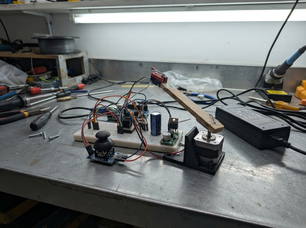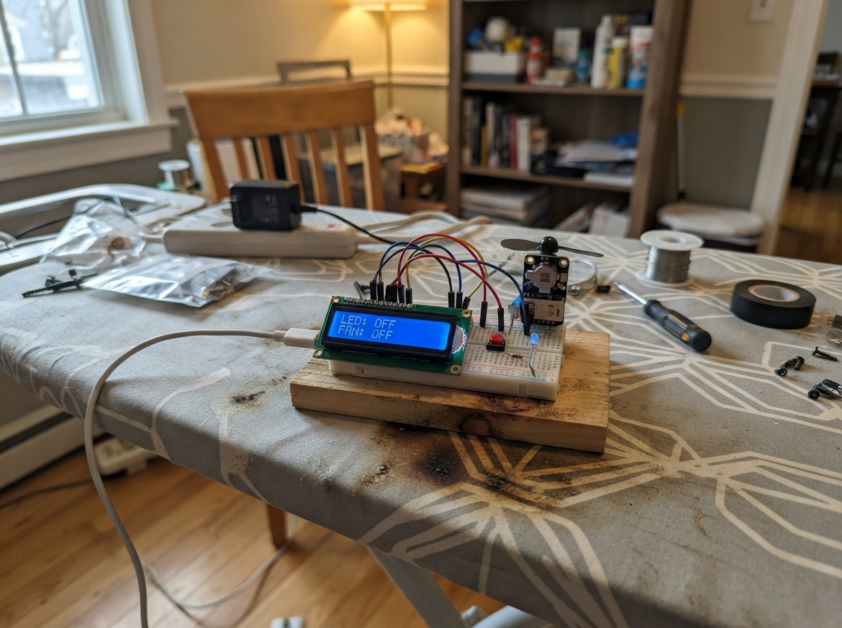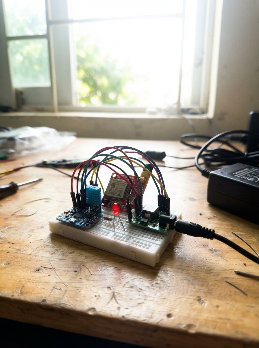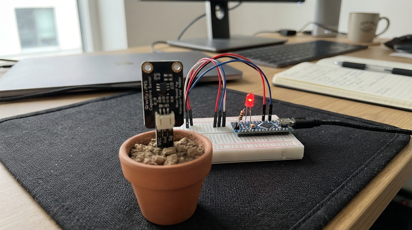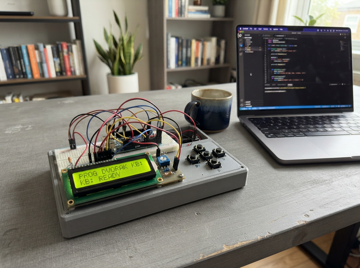
This project builds a compact Dvorak keyboard paired with an Arduino Uno and 16x2 LCD display, designed to teach command-line skills through interactive lessons. The keyboard uses a 6x6 button matrix wired to the Arduino's digital pins, with the LCD showing lesson prompts and simulated terminal output as users practice typing common Linux commands.
The guide includes a complete wiring diagram showing how to connect the matrix buttons, LCD display with contrast control via potentiometer, and all necessary resistors. Assembly steps walk through organizing the button contacts into rows and columns, connecting the display power and data lines, and verifying the circuit before loading the firmware that maps Dvorak key positions and manages the 12-lesson curriculum.
Wiring diagram
Gather all the parts
Assemble it in 10 steps
1. Gather the remaining parts
Use 36 normally-open momentary buttons total (reuse yours). For extra buttons Steren offers the miniature normally-open red push switch: https://www.steren.com.mx/switch-miniatura-de-push-normalmente-abierto-de-127-vca-color-rojo.html . Buy the Steren ARD-380 parallel LCD, a 101-10K 10 kΩ potentiometer and R220 1/2 220 Ω resistor. You also need a USB cable, suitable mounting board, and wire. The display has no adapter; solder wires directly or fit a header.
- Do not connect any part to household electricity. Use USB 5 V only. Unplug USB before wiring or soldering.
2. Connect display power and contrast
Check the LCD printed pin labels and numbering, not its viewing orientation. Pin 1 VSS goes to GND, pin 2 VDD to 5V. Connect the potentiometer outer legs to 5V and GND; its middle leg goes to LCD pin 3 VO (contrast). LCD pin 5 RW goes to GND (write-only).
- Reversed power can destroy the display.
3. Connect the screen data wires
LCD pin 4 RS → A0 (command or text), pin 6 E → A1 (enable), pin 11 D4 → A2, pin 12 D5 → A3, pin 13 D6 → A4, pin 14 D7 → A5 (four data lines). Leave LCD pins 7–10 unconnected. The analog pins are used as ordinary digital pins here.
4. Connect the backlight safely
5V → 220 Ω resistor → LCD pin 15 A (backlight positive). LCD pin 16 K goes to GND. The resistor can face either direction.
5. Identify the button contacts
Each button needs two electrically separate contacts, A and B. On a four-leg tactile button, two legs are already joined on each contact. Use one leg from each separate contact; leave the duplicate legs unused. If uncertain, verify the pairs with continuity testing before wiring. On a two-terminal Steren switch use one terminal for A and one for B. Buttons have no polarity.
- A latching on/off switch is not suitable; the button must spring back to open when released.
6. Wire the six scan rows
For buttons 01–06 join contact A to D2; 07–12 to D3; 13–18 to D4; 19–24 to D5; 25–30 to D6; 31–36 to D7. These are electrical groups, independent of the physical keyboard rows. Do not connect button contacts directly to power or GND.
7. Wire the six scan columns
Contact B: buttons 01,07,13,19,25,31 → D8; 02,08,14,20,26,32 → D9; 03,09,15,21,27,33 → D10; 04,10,16,22,28,34 → D11; 05,11,17,23,29,35 → D12; 06,12,18,24,30,36 → D13. Leave D0 and D1 free for USB programming. Internal pull-up resistors are used.
8. Arrange and label the keypad
Arrange three physical rows of ten: 01–10 = ; , . p y f g c r l; 11–20 = a o e u i d h t n s; 21–30 = ' q j k x b m w v z. A fourth row holds 31 SPACE, 32 BACK, 33 ENTER, 34 SHIFT, 35 FN, 36 LESSON. This is a compact Programmer Dvorak adaptation, not a full-size keyboard. SHIFT and FN are pressed and released before the character, never held together. LESSON restarts the course.
9. Check the assembled circuit
Inspect solder joints for shorts. Power by USB and slowly turn the contrast knob until letters appear. Top line shows the exact task; bottom line shows your typing. Press ENTER to check. On success, read the simulated result and press ENTER again for the next lesson. After a mistake, use BACK to edit and retry. Type one button at a time.
- There are 12 guided lessons. This validates the displayed command, not arbitrary Linux syntax. No real files are created; lesson state resets when power is removed.
- The input limit is 48 characters. The last 15 typed characters remain visible. S means Shift is ready, F means Fn, and N means Fn plus Shift.
10. Keep the symbol labels with your keypad
# Compact Programmer Dvorak key labels Tap and release Shift or Fn before the character. Tap Fn, then Shift, then a key for digits. Never hold multiple buttons. 01: ; Fn: & Fn+Shift: 7 02: , Fn: [ Fn+Shift: 5 03: . Fn: { Fn+Shift: 3 04: p Fn: } Fn+Shift: 1 05: y Fn: ( Fn+Shift: 9 06: f Fn: = Fn+Shift: 0 07: g Fn: * Fn+Shift: 2 08: c Fn: ) Fn+Shift: 4 09: r Fn: + Fn+Shift: 6 10: l Fn: ] Fn+Shift: 8 11: a Fn: ! 12: o Fn: # 13: e Fn: $ 14: u Fn: @ 15: i Fn: / 16: d Fn: - 17: h Fn: \ 18: t Fn: ` 19: n Fn: ~ 20: s Fn: : 21: ' Fn: % 22: q Fn: ^ 23: j Fn: | 24: k Fn: _ 25: x Fn: ? 26: b Fn: < 27: m Fn: > 28: w Fn: " 29: v Fn: . 30: z Fn: , 31 Space; 32 Backspace; 33 Enter; 34 Shift; 35 Fn; 36 Restart lessons. Physical rows: 01–10, 11–20, 21–30, then six controls. Shift capitalizes letters and changes ; , . and apostrophe to : < > and double quote. This is a compact adaptation, not a full-size layout. Type the exact task on the top line and press Enter. On success, Enter advances. Tasks: pwd, ls, mkdir practice, cd practice, touch notes.txt, ls, cat notes.txt, echo hello, rm notes.txt, cd .., rmdir practice, clear. Only these guided tasks are validated. Outputs are illustrative: this is not Linux and has no filesystem. Progress resets at power-off.
Review all connections
1. Connections between "lcd" and "Arduino"
2. Connections between "contrast" and "Arduino"
3. Connections between "backlight_r" and "Arduino"
4. Connections between "key01" and "Arduino"
5. Connections between "key02" and "Arduino"
6. Connections between "key03" and "Arduino"
7. Connections between "key04" and "Arduino"
8. Connections between "key05" and "Arduino"
9. Connections between "key06" and "Arduino"
10. Connections between "key07" and "Arduino"
11. Connections between "key08" and "Arduino"
12. Connections between "key09" and "Arduino"
13. Connections between "key10" and "Arduino"
14. Connections between "key11" and "Arduino"
15. Connections between "key12" and "Arduino"
16. Connections between "key13" and "Arduino"
17. Connections between "key14" and "Arduino"
18. Connections between "key15" and "Arduino"
19. Connections between "key16" and "Arduino"
20. Connections between "key17" and "Arduino"
21. Connections between "key18" and "Arduino"
22. Connections between "key19" and "Arduino"
23. Connections between "key20" and "Arduino"
24. Connections between "key21" and "Arduino"
25. Connections between "key22" and "Arduino"
26. Connections between "key23" and "Arduino"
27. Connections between "key24" and "Arduino"
28. Connections between "key25" and "Arduino"
29. Connections between "key26" and "Arduino"
30. Connections between "key27" and "Arduino"
31. Connections between "key28" and "Arduino"
32. Connections between "key29" and "Arduino"
33. Connections between "key30" and "Arduino"
34. Connections between "key31" and "Arduino"
35. Connections between "key32" and "Arduino"
36. Connections between "key33" and "Arduino"
37. Connections between "key34" and "Arduino"
38. Connections between "key35" and "Arduino"
39. Connections between "key36" and "Arduino"
Deploy the firmware
#include <Arduino.h>
#include <LiquidCrystal.h>
#include <avr/pgmspace.h>
#include <ctype.h>
LiquidCrystal lcd(A0,A1,A2,A3,A4,A5);
// Wiring verified: shared row contacts D2-D7, shared columns D8-D13.
// LCD RS/E/D4/D5/D6/D7 use A0/A1/A2/A3/A4/A5.
const uint8_t rows[6]={2,3,4,5,6,7};
const uint8_t cols[6]={8,9,10,11,12,13};
const char normal[] PROGMEM=";,.pyfgcrlaoeuidhtns'qjkxbmwvz";
const char symbols[] PROGMEM="&[{}(=*)+]!#$@/-\\`~:%^|_?<>\".,";
const char numbers[] PROGMEM="7531902468";
const char l0[] PROGMEM="pwd";
const char l1[] PROGMEM="ls";
const char l2[] PROGMEM="mkdir practice";
const char l3[] PROGMEM="cd practice";
const char l4[] PROGMEM="touch notes.txt";
const char l5[] PROGMEM="ls";
const char l6[] PROGMEM="cat notes.txt";
const char l7[] PROGMEM="echo hello";
const char l8[] PROGMEM="rm notes.txt";
const char l9[] PROGMEM="cd ..";
const char l10[] PROGMEM="rmdir practice";
const char l11[] PROGMEM="clear";
const char* const lessons[] PROGMEM={l0,l1,l2,l3,l4,l5,l6,l7,l8,l9,l10,l11};
const char o0[] PROGMEM="/home/student";
const char o1[] PROGMEM="(empty folder)";
const char o2[] PROGMEM="Directory made";
const char o3[] PROGMEM="In practice/";
const char o4[] PROGMEM="File created";
const char o5[] PROGMEM="notes.txt";
const char o6[] PROGMEM="(empty file)";
const char o7[] PROGMEM="hello";
const char o8[] PROGMEM="File removed";
const char o9[] PROGMEM="/home/student";
const char o10[] PROGMEM="Folder removed";
const char o11[] PROGMEM="Course complete!";
const char* const outputs[] PROGMEM={o0,o1,o2,o3,o4,o5,o6,o7,o8,o9,o10,o11};
char input[49]={0}, previous[2][17]={{0}};
uint8_t used=0,lesson=0;
bool shiftNext=false,fnNext=false,passed=false,wrong=false,dirty=true;
const char* flashItem(const char* const* table,uint8_t i){return (const char*)pgm_read_ptr(table+i);}
void line(uint8_t row,const char* text){
 char padded[17]; memset(padded,' ',16); padded[16]=0;
 for(uint8_t i=0;i<16 && text[i];i++)padded[i]=text[i];
 if(strcmp(previous[row],padded)){lcd.setCursor(0,row);lcd.print(padded);strcpy(previous[row],padded);}
}
void render(){
 if(!dirty)return;dirty=false;
 char top[49];
 if(passed){strcpy_P(top,flashItem(outputs,lesson));line(0,top);line(1,"ENTER: next task");return;}
 if(wrong)strcpy(top,"Retry exact task");
 else strcpy_P(top,flashItem(lessons,lesson));
 line(0,top);
 char bottom[17];bottom[0]=fnNext?(shiftNext?'N':'F'):(shiftNext?'S':'>');
 uint8_t start=used>15?used-15:0;
 strcpy(bottom+1,input+start);line(1,bottom);
}
// Only one selected row is driven LOW; all other rows are high impedance.
// Multiple simultaneous closures are rejected until every key is released.
int scan(){
 int found=-1;
 for(uint8_t r=0;r<6;r++){
  digitalWrite(rows[r],LOW);pinMode(rows[r],OUTPUT);delayMicroseconds(50);
  for(uint8_t c=0;c<6;c++)if(!digitalRead(cols[c])){if(found==-1)found=r*6+c;else found=-2;}
  pinMode(rows[r],INPUT);
 }
 return found;
}
void resetInput(){used=0;input[0]=0;wrong=false;shiftNext=fnNext=false;dirty=true;}
void key(int k){
 dirty=true;
 if(k==35){lesson=0;passed=false;resetInput();return;}
 if(k==32){
  if(passed){lesson=(lesson+1)%12;passed=false;resetInput();}
  else {passed=strcmp_P(input,flashItem(lessons,lesson))==0;wrong=!passed;}
  return;
 }
 if(passed)return;
 if(k==33){shiftNext=!shiftNext;return;}
 if(k==34){fnNext=!fnNext;return;}
 wrong=false;
 if(k==31){if(used)input[--used]=0;return;}
 char ch=' ';
 if(k<30){
  ch=pgm_read_byte((fnNext?symbols:normal)+k);
  if(fnNext && shiftNext && k<10)ch=pgm_read_byte(numbers+k);
  else if(!fnNext && shiftNext){if(ch==';')ch=':';else if(ch==',')ch='<';else if(ch=='.')ch='>';else if(ch=='\'')ch='"';else ch=toupper(ch);}
 }
 if(used<48){input[used++]=ch;input[used]=0;}
 shiftNext=fnNext=false;
}
void setup(){
 for(uint8_t i=0;i<6;i++){pinMode(rows[i],INPUT);pinMode(cols[i],INPUT_PULLUP);}
 lcd.begin(16,2);render();
}
void loop(){
 static int candidate=-1,stable=-1;static unsigned long changed=0;static bool armed=true;
 int raw=scan();
 if(raw==-2)armed=false;
 if(raw!=candidate){candidate=raw;changed=millis();}
 if(millis()-changed>=30 && stable!=candidate){
  stable=candidate;
  if(stable==-1)armed=true;
  else if(stable>=0 && armed){armed=false;key(stable);}
 }
 render();
}
Remix this project
Make it yours in one click
Open a full copy of this project in your own Schematik workspace, diagram, code, parts, and assembly steps included. Swap the sensor, add features, or redesign the whole thing with AI. The author's original stays untouched.