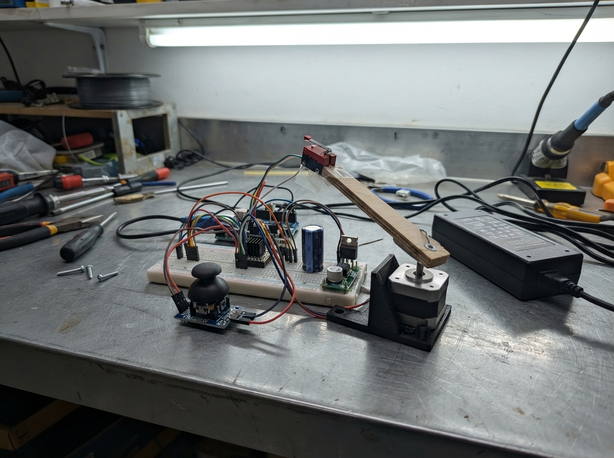
This robotic ball deflector combines precise motor control with solenoid-based striking to create an automated sports training device. Built around an Arduino Uno, it uses a PS2 joystick for lateral positioning via a NEMA 17 stepper motor, while an independent 12V solenoid delivers timed strikes. The guide provides a complete wiring diagram, parts list with fused power distribution, and firmware with debounced firing logic and acceleration profiles.
Assembly progresses from joystick calibration through power protection and motor setup, then integrates the solenoid strike mechanism with safety interlocks. Testing begins without load to verify motor direction and solenoid timing, then proceeds with the full mechanical assembly. Builders will learn stepper motor control, relay switching for high-current loads, and real-time input handling on a microcontroller.
Wiring diagram
Gather all the parts
Assemble it in 10 steps
1. Joystick
Bloque «Joystick»: mando por cable de cinco conductores. +5V a 5V, GND a GND, VRX a A0 (posición lateral), VRY a A1 (reservado), SW a D5 (botón contra GND). Mantener centrado al encender.
2. Arduino Uno y A4988
Bloque «Arduino Uno y A4988»: STEP a D2, DIR a D3, EN a D4; resistencia r_enable de 10 kΩ entre EN y 5V para deshabilitar durante el arranque. VDD a 5V, GND_2 a GND. Unir RST con SLP y con 5V. MS1/MS2/MS3 a GND: paso completo.
3. Alimentación protegida
Con todo desenchufado: positivo de la fuente de 12 V a fusible general T5 A, luego interruptor general. Desde su salida distribuir tres ramas: fusible motor T3.15 A hacia VMOT, fusible solenoide T2.5 A hacia bobina, y entrada positiva del buck. Negativo común en estrella. Usar cable flexible de potencia de 0.75 mm² y bornes; no pasar potencia por protoboard ni por el Arduino.
4. Ajustar los 8 V del Arduino
Sin conectar VIN, medir y ajustar salida del buck a 8.0 V. Apagar y conectar VOUT+ a VIN y VOUT- a GND. El joystick y la lógica reciben 5 V del Uno; nunca 12 V. Usar solamente la salida aislada de un adaptador cerrado.
5. Motor y solenoide: movimiento lateral
Bloque «Motor y solenoide», circuito MOTOR: NEMA 17 fijo mueve exclusivamente la banda GT2 del portero amarillo. Identificar con multímetro cada pareja de bobina, sin suponer colores: pareja A a 1A/1B y pareja B a 2A/2B. Condensador de 220 µF/35 V directamente entre VMOT (+) y GND de potencia (-), lo más cerca posible. Colocar disipador sin cortocircuitar terminales.
- Nunca conectar o desconectar motor con alimentación; puede destruir el A4988. Condensador invertido puede reventar.
6. Limitar corriente antes de cargar
Ajustar el límite del A4988 según motor y refrigeración: empezar en 1 A. Para Pololu Black con Rs=0.068 Ω, VREF=8×Imax×Rs: 0.544 V para 1 A; máximo objetivo 0.816 V para límite de 1.5 A. No trasladar estos voltajes a clones con otra Rs. En paso completo circula aproximadamente 70% de Imax por bobina: no aumentar el límite por encima de 1.5 A para compensarlo. El disipador no garantiza servicio continuo a esa corriente; reducir corriente si hay calentamiento o paradas térmicas.
- Motor y driver pueden quemar al tacto. Si el par a corriente reducida no basta, se requiere mejor refrigeración o rediseñar el driver.
7. Topes de seguridad normalmente cerrados
Izquierdo: NC a D8 y COM a GND; derecho: NC a D9 y COM a GND. Dejar NO sin conectar. Ajustar para abrir antes del tope mecánico, con margen de frenado. Cable roto también bloquea ese sentido. No son un sistema de seguridad certificado.
8. Motor y solenoide: golpe independiente
Circuito SOLENOIDE: positivo después del fusible T2.5 A a POS de bobina; RET al DRAIN del IRLZ44N. SOURCE a negativo común. D6 a resistencia 220 Ω y luego GATE; 10 kΩ entre GATE y SOURCE. Diodo 1N5822 directamente en bobina: banda/cátodo al POS, ánodo al RET/drenador. En IRLZ44N TO-220 frontal rotulado, patas abajo: GATE izquierda, DRAIN centro (también pestaña), SOURCE derecha. No confundir con IRFZ44N.
- Invertir el diodo cortocircuita la alimentación al activar. Aislar la pestaña metálica del MOSFET: está conectada al drenador.
9. Montaje móvil y primera prueba
El solenoide va en el carro y solo golpea la pelota. Guiar su cable flexible con alivio de tracción para que no alcance banda ni ranura. Escoger solenoide de 12 V ≤2 A con fuerza y carrera especificadas: 20 N no está garantizado por consumir 2 A. Pulso inicial 60 ms, mínimo 1 segundo entre golpes; reducir si la ficha exige menor ciclo. Si la corriente nominal difiere de 2 A, revisar y redimensionar fuente, MOSFET, diodo y fusibles.
10. Verificación sin banda y luego con carga
Primero probar motor sin banda: joystick a la derecha debe girar en sentido de desplazamiento derecho. Accionar el final derecho debe impedir ese giro y permitir el contrario; repetir izquierdo. Si sentido invertido, apagar y permutar una sola pareja de bobina. Después montar banda y verificar a baja velocidad con manos fuera. Con ambos finales abiertos no debe moverse. Botón mantenido debe dar un solo golpe. Apagar interruptor para detener potencia; con USB conectado el Uno puede seguir encendido.
Review all connections
1. Connections between "fuente" and "Arduino"
2. Connections between "fusible_general" and "Arduino"
3. Connections between "interruptor" and "Arduino"
4. Connections between "fusible_motor" and "Arduino"
5. Connections between "driver" and "Arduino"
6. Connections between "condensador" and "Arduino"
7. Connections between "fusible_sol" and "Arduino"
8. Connections between "solenoide" and "Arduino"
9. Connections between "mosfet" and "Arduino"
10. Connections between "diodo" and "Arduino"
11. Connections between "r_gate" and "Arduino"
12. Connections between "r_down" and "Arduino"
13. Connections between "buck" and "Arduino"
14. Connections between "joystick" and "Arduino"
15. Connections between "r_enable" and "Arduino"
16. Connections between "limite_izq" and "Arduino"
17. Connections between "limite_der" and "Arduino"
Deploy the firmware
#include <Arduino.h>
constexpr uint8_t STEP=2, DIR=3, ENABLE=4, BUTTON=5, SOL=6, LEFT=8, RIGHT=9;
constexpr bool RIGHT_LEVEL=HIGH; // Verificar sin banda; invertir si gira al revés.
constexpr uint16_t PULSE_MS=60, COOLDOWN_MS=1000;
constexpr float MAX_SPEED=500.0f, ACCEL=700.0f;
int center=512;
float speed=0;
uint32_t updateMs=0, sampleMs=0, lastStep=0, shotStart=0, lastShot=0, buttonChange=0;
bool firing=false, everShot=false, rawPrev=true, stable=true, armed=false;
int axis=512;
void setup(){
 digitalWrite(SOL,LOW); pinMode(SOL,OUTPUT);
 digitalWrite(ENABLE,HIGH); pinMode(ENABLE,OUTPUT);
 pinMode(STEP,OUTPUT); digitalWrite(STEP,LOW);
 pinMode(DIR,OUTPUT); digitalWrite(DIR,LOW);
 pinMode(BUTTON,INPUT_PULLUP); pinMode(LEFT,INPUT_PULLUP); pinMode(RIGHT,INPUT_PULLUP);
 pinMode(A0,INPUT); pinMode(A1,INPUT);
 // Joystick centrado durante el arranque; una calibración extrema no permite mover.
 long sum=0; for(uint8_t i=0;i<32;i++){sum+=analogRead(A0); delay(2);}
 center=sum/32;
 armed=(center>350 && center<674);
 updateMs=millis();
}
void loop(){
 const uint32_t now=millis();
 if(firing && uint32_t(now-shotStart)>=PULSE_MS){digitalWrite(SOL,LOW); firing=false;}
 bool raw=digitalRead(BUTTON);
 if(raw!=rawPrev){rawPrev=raw; buttonChange=now;}
 if(uint32_t(now-buttonChange)>=25 && raw!=stable){
  stable=raw;
  if(!stable && !firing && (!everShot || uint32_t(now-lastShot)>=COOLDOWN_MS)){
   digitalWrite(SOL,HIGH); firing=true; shotStart=lastShot=now; everShot=true;
  }
 }
 if(uint32_t(now-sampleMs)>=5){sampleMs=now; axis=analogRead(A0); (void)analogRead(A1);}
 // NC cerrado = LOW. Pulsado o cable roto = HIGH. Parada sin rampa hacia ese extremo.
 bool left=digitalRead(LEFT)==HIGH, right=digitalRead(RIGHT)==HIGH;
 if((speed<0 && left)||(speed>0 && right))speed=0;
 int delta=axis-center;
 float target=0;
 if(armed && abs(delta)>60){
  target=(delta>0?1.0f:-1.0f)*min(1.0f,(abs(delta)-60)/400.0f)*MAX_SPEED;
 }
 if((target<0 && left)||(target>0 && right))target=0;
 if(uint32_t(now-updateMs)>=5){
  float dt=min(uint32_t(now-updateMs),uint32_t(20))/1000.0f; updateMs=now;
  float change=ACCEL*dt;
  if(speed<target)speed=min(speed+change,target);
  else if(speed>target)speed=max(speed-change,target);
 }
 if(abs(speed)<1){digitalWrite(ENABLE,HIGH);lastStep=micros();return;}
 if((speed<0 && left)||(speed>0 && right)){speed=0;digitalWrite(ENABLE,HIGH);return;}
 digitalWrite(ENABLE,LOW);
 uint32_t us=micros(), interval=uint32_t(1000000.0f/abs(speed));
 if(uint32_t(us-lastStep)>=interval){
  digitalWrite(DIR,speed>0?RIGHT_LEVEL:!RIGHT_LEVEL);
  delayMicroseconds(3);
  // Releer límites justo antes del pulso.
  if(digitalRead(speed>0?RIGHT:LEFT)==LOW){
   digitalWrite(STEP,HIGH);delayMicroseconds(3);digitalWrite(STEP,LOW);
  }
  lastStep=us;
 }
}

// Pines revisados: STEP D2, DIR D3, EN D4; VDD 5 V separado de VMOT.
Remix this project
Make it yours in one click
Open a full copy of this project in your own Schematik workspace, diagram, code, parts, and assembly steps included. Swap the sensor, add features, or redesign the whole thing with AI. The author's original stays untouched.