Community project
Heart Rate Monitor
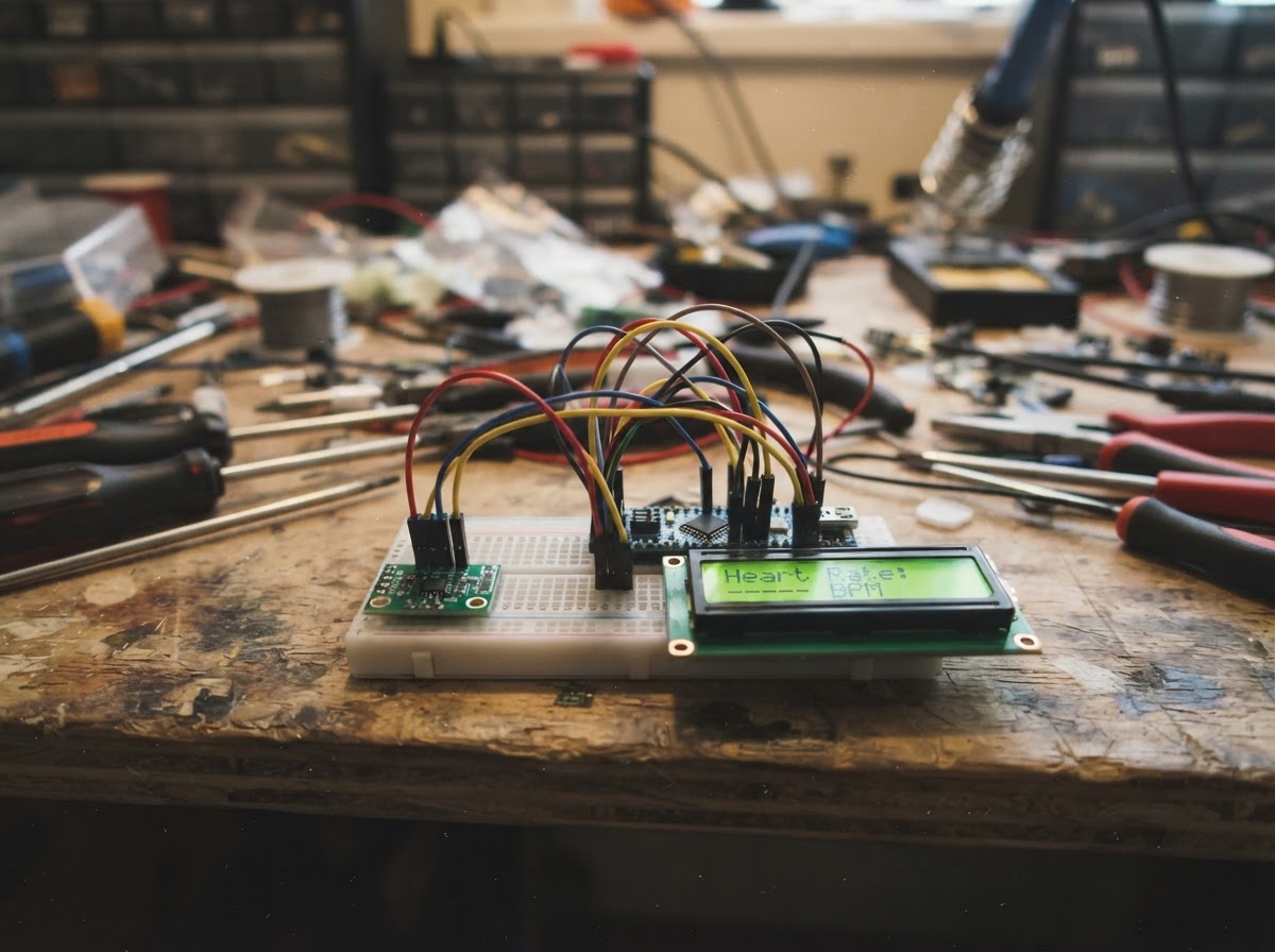
This heart rate monitor uses an ESP32 microcontroller to detect and display your pulse in real time. The MAX30102 optical sensor reads blood flow through a fingertip, while a 16x2 LCD screen shows the current heart rate in beats per minute. The guide includes a complete wiring diagram, parts list, and ready-to-use firmware.
Following the assembly steps, the sensor will prompt you to place your finger on the MAX30102, then calculate and display your heart rate with a rolling average for stable readings. This project demonstrates how optical sensors and microcontrollers work together to create a practical health monitoring device.
Wiring diagram

Gather all the parts
Assemble it in 4 steps
1. Keep the ESP32 unpowered while wiring
Disconnect the ESP32 DevKit v1 from USB before making connections. Use a breadboard and short jumper wires.
- Both I2C modules use the same two signal lines.
- Use only a 3.3 V-safe I2C LCD module. A typical LCD backpack powered at 5 V can pull SDA/SCL up to 5 V and permanently damage the ESP32.
2. Wire the MAX30102 sensor
Connect max30102_1 VCC to the ESP32 3V3 pin, GND to ESP32 GND, SDA to GPIO 21, and SCL to GPIO 22. Leave INT unconnected.
- Place the sensor so its LED window can contact the pad of a fingertip.
- Do not supply the MAX30102 breakout from 5 V unless its own board documentation explicitly says it accepts 5 V and its I2C pins are level-safe.
3. Wire the 3.3 V-safe LCD
Connect lcd_1 VCC to ESP32 3V3, GND to ESP32 GND, SDA to GPIO 21, and SCL to GPIO 22. These SDA and SCL connections are shared with the MAX30102.
- If the display lights but shows no text, adjust its contrast trimmer slowly.
- The code assumes I2C address 0x27; some backpacks use 0x3F.
- Do not connect a normal 5 V LCD I2C backpack directly to GPIO 21/22. Use a verified 3.3 V-safe LCD or a correctly wired bidirectional I2C level shifter.
4. Power and test
Recheck that all grounds are common, then connect the ESP32 by USB. Use Schematik’s Deploy button to flash the project. Put a fingertip gently and steadily over the MAX30102 window; avoid pressing hard or moving while it measures.
- The display first says to place a finger, then reports a smoothed BPM reading after a few detected beats.
- This is an educational wellness project, not a medical device. Do not use its reading for diagnosis, treatment, or emergency decisions.
Review all connections
1. Connections between "max30102_1" and "ESP32"
2. Connections between "lcd_1" and "ESP32"
Deploy the firmware
#include <Arduino.h>
#include <Wire.h>
#include <LiquidCrystal_I2C.h>
#include "MAX30105.h"
#include "heartRate.h"


// Forward declarations
void writeLine(uint8_t row, const String &text, String &previous);
void updateDisplay();

constexpr uint8_t I2C_SDA_PIN = 21;
constexpr uint8_t I2C_SCL_PIN = 22;
constexpr uint8_t LCD_ADDRESS = 0x27;
constexpr uint32_t FINGER_THRESHOLD = 50000;
constexpr uint32_t DISPLAY_INTERVAL_MS = 250;

MAX30105 particleSensor;
LiquidCrystal_I2C lcd(LCD_ADDRESS, 16, 2);

uint32_t lastBeatMs = 0;
uint32_t lastDisplayMs = 0;
float bpm = 0.0F;
float averagedBpm = 0.0F;
uint8_t bpmSamples[4] = {0, 0, 0, 0};
uint8_t sampleIndex = 0;
bool fingerPresent = false;
String lastLine1;
String lastLine2;

void writeLine(uint8_t row, const String &text, String &previous) {
  String padded = text;
  while (padded.length() < 16) {
    padded += ' ';
  }
  padded = padded.substring(0, 16);
  if (padded != previous) {
    lcd.setCursor(0, row);
    lcd.print(padded);
    previous = padded;
  }
}

void updateDisplay() {
  if (!fingerPresent) {
    writeLine(0, "Place finger", lastLine1);
    writeLine(1, "on MAX30102", lastLine2);
    return;
  }

  writeLine(0, "Heart rate", lastLine1);
  if (averagedBpm >= 30.0F && averagedBpm <= 220.0F) {
    writeLine(1, String((int)(averagedBpm + 0.5F)) + " BPM", lastLine2);
  } else {
    writeLine(1, "Measuring...", lastLine2);
  }
}

void setup() {
  Serial.begin(115200);
  Wire.begin(I2C_SDA_PIN, I2C_SCL_PIN);

  lcd.init();
  lcd.backlight();
  writeLine(0, "MAX30102 monitor", lastLine1);
  writeLine(1, "Starting...", lastLine2);

  if (!particleSensor.begin(Wire, I2C_SPEED_STANDARD)) {
    writeLine(0, "MAX30102 error", lastLine1);
    writeLine(1, "Check I2C wires", lastLine2);
    while (true) {
      delay(1000);
    }
  }

  particleSensor.setup(60, 4, 2, 100, 411, 4096);
  particleSensor.setPulseAmplitudeRed(0x1F);
  particleSensor.setPulseAmplitudeIR(0x1F);
  particleSensor.setPulseAmplitudeGreen(0);
  updateDisplay();
}

void loop() {
  const long irValue = particleSensor.getIR();
  fingerPresent = irValue > FINGER_THRESHOLD;

  if (fingerPresent && checkForBeat(irValue)) {
    const uint32_t now = millis();
    if (lastBeatMs != 0) {
      bpm = 60.0F / ((now - lastBeatMs) / 1000.0F);
      if (bpm >= 30.0F && bpm <= 220.0F) {
        bpmSamples[sampleIndex] = (uint8_t)bpm;
        sampleIndex = (sampleIndex + 1) % 4;
        uint16_t total = 0;
        uint8_t count = 0;
        for (uint8_t i = 0; i < 4; i++) {
          if (bpmSamples[i] > 0) {
            total += bpmSamples[i];
            count++;
          }
        }
        if (count > 0) {
          averagedBpm = (float)total / count;
        }
      }
    }
    lastBeatMs = now;
  }

  if (!fingerPresent) {
    averagedBpm = 0.0F;
    lastBeatMs = 0;
    for (uint8_t i = 0; i < 4; i++) {
      bpmSamples[i] = 0;
    }
  }

  if (millis() - lastDisplayMs >= DISPLAY_INTERVAL_MS) {
    lastDisplayMs = millis();
    updateDisplay();
  }
}
Remix this project
Make it yours in one click
Open a full copy of this project in your own Schematik workspace — diagram, code, parts, and assembly steps included. Swap the sensor, add features, or redesign the whole thing with AI. The author's original stays untouched.