Community project
Indoor Elderly Assistance Robot
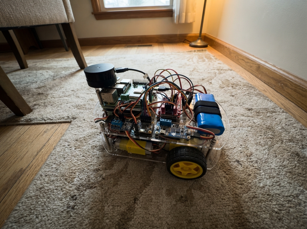
This indoor assistance robot delivers medicine and supplies to elderly residents in care facilities. Built around an ESP32 safety controller paired with a Raspberry Pi 4 navigation computer, the robot combines real-time motor control, battery management, and obstacle detection with SLAM-based autonomous routing. The guide provides a complete wiring diagram, parts list, firmware for the ESP32 safety layer, and step-by-step assembly instructions for the rolling base, power distribution, motor drive section, and sensor integration.
The robot uses dual 6 V encoder gearmotors driven by a TB6612FNG H-bridge, an MPU-6050 IMU for stability monitoring, an INA219 current sensor for battery health tracking, and a RPLIDAR A1 for 2D mapping and collision avoidance. Power comes from a protected 18650 Li-ion battery pack with regulated rails for the motors, logic, and compute boards. Safety features include emergency stop, bumper switches, and watchdog timeouts to ensure reliable operation in shared indoor spaces.
Wiring diagram

Gather all the parts
Assemble it in 8 steps
1. Build the rolling base and medicine tray
Fit the left_motor and right_motor on opposite sides of a low, rigid chassis, then attach the wheels and a rear caster. Bolt a shallow tray with raised sides above the chassis; add a lid, elastic strap, or latch so a medicine box cannot slide out while the robot turns.
- Keep the battery low and centered between the wheels so the robot is less likely to tip.
- Leave a clear, high mounting position at the front for the LiDAR so the tray does not block its view.
- Do not carry loose tablets or an open drink on the tray; a sudden stop can throw them out.
- Do not treat this robot as a mobility aid or let a person lean on it.
2. Install the battery, protection board, and charger
Secure battery_pack in a covered holder. Connect PACK+ to bms B+ (battery positive), MID to bms BM (the join between the two cell groups), and PACK- to bms B- (battery negative). Connect charger DC+ to bms P+ and charger DC- to bms P-; mount the charger connector where it is easy to reach or align with a dock.
- Use a prebuilt matched 2S2P pack with a proper fuse and insulated leads.
- Label the charger socket clearly as 8.4 V Li-ion charging only.
- Never connect the 8.4 V charger directly to individual cells or reverse the battery leads — that can cause overheating or fire.
- Do not charge the robot unattended or inside a sealed enclosure.
3. Make the regulated power rails
Connect bms P+ to battery_monitor VIN+ (battery current measurement), then connect battery_monitor VIN- to both buck_5v VIN+ and buck_6v VIN+. Join every regulator negative pin, bms P-, and module ground to the same GND return. Set buck_5v to 5.1 V before attaching the navigation computer, and set buck_6v to 6.0 V before attaching the motors.
- Measure each regulator output with a multimeter first: 5.1 V for logic/USB equipment and 6.0 V for the motor rail.
- Use thicker wire for the battery, BMS, buck converters, emergency stop, driver VM, and motors.
- Do not connect a regulator output until its voltage has been measured; an incorrectly adjusted buck converter can destroy the Raspberry Pi or motors.
- Keep battery wiring away from sharp chassis edges so vibration cannot wear through insulation.
4. Wire the motor cutoff and drive section
Connect buck_6v VOUT+ to estop NC IN, then estop NC OUT to motor_driver VM; this makes pressing the mushroom button physically remove motor power. Connect motor_driver A01 and A02 to left_motor M+ and M-, and B01 and B02 to right_motor M+ and M-. Connect motor_driver VCC to 3V3 (logic power), GND to GND (ground), AIN1 to GPIO25 (left direction), AIN2 to GPIO26 (left direction), PWMA to GPIO27 (left speed), BIN1 to GPIO13 (right direction), BIN2 to GPIO14 (right direction), PWMB to GPIO32 (right speed), and STBY to GPIO33 (driver enable).
- With the wheels raised off the table for the first test, command a slow forward motion; swap the two motor wires on one motor if it turns the wrong direction.
- Place the emergency-stop mushroom button where the elderly person or helper can reach it quickly.
- Pressing the emergency-stop must stop both wheels immediately; do not operate the robot until this is true.
- Keep fingers, clothing, and wires clear of the wheels during tests.
5. Connect the ESP32 safety controller and notification parts
Connect the ESP32 3V3 and GND rails to the shared logic rails. Connect imu VIN to 3V3 (power), GND to GND (ground), SDA to GPIO21 (data), and SCL to GPIO22 (clock). Connect battery_monitor VCC to 3V3 (power), GND to GND (ground), SDA to GPIO21 (data), and SCL to GPIO22 (clock). Connect buzzer VCC to 3V3 (power), GND to GND (ground), and SIG to GPIO4 (alert). Connect status_led VCC to 3V3 (power), GND to GND (ground), RED to GPIO12 (fault light), and GREEN to GPIO15 (moving light). Connect the emergency-stop auxiliary contact to GPIO23 (stop-state signal) using its 10 kΩ pull-up resistor to 3V3.
- Mount the IMU flat near the center of the chassis, with its arrow pointing toward the robot front.
- The LED module must include its own resistors; bare LEDs require one resistor on each color lead.
- Do not use a bare LED without a series resistor — it can burn out the LED or damage the controller pin.
- The 3.3 V ESP32 pins must never be connected directly to a 5 V signal.
6. Install the bumpers and encoder wiring
Mount front_bumper so either front edge presses a switch before the chassis reaches an obstacle. Wire its GND to GND (ground), LEFT SENSE to GPIO34 (left collision signal), and RIGHT SENSE to GPIO35 (right collision signal); its resistor board supplies the needed 3.3 V-safe pull-ups. Connect each motor encoder VCC to 5V (power) and ENC GND to GND (ground). Connect left_motor ENC A and ENC B to navigation_pi LEFT ENC A and LEFT ENC B (wheel distance signals), and connect right_motor ENC A and ENC B to navigation_pi RIGHT ENC A and RIGHT ENC B (wheel distance signals).
- Use the intended 3.3 V-safe encoder outputs or add proper level shifters if your encoder board produces 5 V pulses.
- Route encoder wires away from motor wires to reduce false counts.
- A pressed bumper or broken bumper wire must be treated as a stop condition; do not bypass these switches.
- Never feed a 5 V encoder pulse directly into a Raspberry Pi GPIO pin — it can permanently damage the Pi.
7. Fit the navigation computer and LiDAR
Connect buck_5v VOUT+ to navigation_pi 5V IN (power) and VOUT- to navigation_pi GND (ground). Connect navigation_pi UART TX to ESP32 GPIO16 (motion commands) and navigation_pi UART RX to ESP32 GPIO17 (safety status). Connect lidar USB DATA to navigation_pi USB LIDAR (map data), lidar 5V to 5V (power), and lidar GND to GND (ground). Mount the LiDAR level and above the tray rim, facing into open space.
- Use a short USB lead with strain relief so vibration does not loosen it.
- Keep the LiDAR's rotating window clean and uncovered; it is the robot's main view of walls and furniture.
- Do not power the Raspberry Pi from an unmeasured battery rail; it needs the regulated 5.1 V supply.
- Do not look closely into the LiDAR window or cover it while the scanner is running.
8. Perform a safe bench test before floor driving
Raise the chassis so the wheels cannot touch the floor. Power on, verify the red light is on until a valid drive command arrives, press the emergency-stop, and confirm the motor driver loses its 6 V supply. Then test the bumper switches, buzzer, battery reading, LiDAR scan, and low-speed wheel direction. Only after these tests should the robot map one clear room at walking pace.
- Set the navigation software speed limit to a slow walking pace or less, about 0.2 m/s, and keep a helper beside it for the first mapped route.
- Create the bed, bedroom, kitchen, medicine-table, living-room, and charger locations in the dashboard only after the map is stable.
- If localization is lost, battery is low, a bumper is hit, or sensor data stops, the robot must stop rather than guessing where to drive.
- The charger is not an autonomous docking system in this prototype; guide it to the connector/dock until a separately tested docking alignment system is added.
Review all connections
1. Connections between "battery_pack" and "ESP32"
2. Connections between "charger" and "ESP32"
3. Connections between "bms" and "ESP32"
4. Connections between "battery_monitor" and "ESP32"
5. Connections between "buck_5v" and "ESP32"
6. Connections between "buck_6v" and "ESP32"
7. Connections between "estop" and "ESP32"
8. Connections between "motor_driver" and "ESP32"
9. Connections between "left_motor" and "ESP32"
10. Connections between "right_motor" and "ESP32"
11. Connections between "imu" and "ESP32"
12. Connections between "navigation_pi" and "ESP32"
13. Connections between "lidar" and "ESP32"
14. Connections between "front_bumper" and "ESP32"
15. Connections between "buzzer" and "ESP32"
16. Connections between "status_led" and "ESP32"
Deploy the firmware
#include <Arduino.h>
#include <Wire.h>

// ESP32 real-time safety and motor controller for the indoor assistance robot.
// The Raspberry Pi performs SLAM, map storage, route planning, and dashboard UI.


// Forward declarations
bool readIna219Register(uint8_t reg, int16_t &value);
float readBusVoltage();
int batteryPercent(float volts);
bool estopPressed();
bool leftBumperPressed();
bool rightBumperPressed();
bool hazardPresent();
void setMotorChannel(int in1, int in2, int pwmPin, int speedValue);
void stopMotors(const char *reason);
void driveMotors(int leftSpeed, int rightSpeed);
void beep(unsigned int durationMs);
void sendStatus();
void handleCommand(String command);

constexpr int LEFT_IN1 = 25;
constexpr int LEFT_IN2 = 26;
constexpr int LEFT_PWM = 27;
constexpr int RIGHT_IN1 = 13;
constexpr int RIGHT_IN2 = 14;
constexpr int RIGHT_PWM = 32;
constexpr int MOTOR_STBY = 33;
constexpr int ESTOP_PIN = 23;
constexpr int BUMPER_LEFT_PIN = 34;
constexpr int BUMPER_RIGHT_PIN = 35;
constexpr int BUZZER_PIN = 4;
constexpr int LED_RED_PIN = 12;
constexpr int LED_GREEN_PIN = 15;
constexpr int I2C_SDA_PIN = 21;
constexpr int I2C_SCL_PIN = 22;
constexpr int PI_UART_RX = 16;
constexpr int PI_UART_TX = 17;

constexpr uint8_t INA219_ADDRESS = 0x40;
constexpr uint32_t COMMAND_TIMEOUT_MS = 500;
constexpr uint8_t MAX_PWM = 115;  // limits the robot to a slow indoor speed

String commandBuffer;
unsigned long lastMotionCommandMs = 0;
unsigned long lastStatusMs = 0;
bool moving = false;
bool safetyStopped = true;

bool readIna219Register(uint8_t reg, int16_t &value) {
  Wire.beginTransmission(INA219_ADDRESS);
  Wire.write(reg);
  if (Wire.endTransmission(false) != 0) return false;
  if (Wire.requestFrom((int)INA219_ADDRESS, 2) != 2) return false;
  value = (int16_t)((Wire.read() << 8) | Wire.read());
  return true;
}

float readBusVoltage() {
  int16_t raw = 0;
  if (!readIna219Register(0x02, raw)) return -1.0f;
  return ((raw >> 3) * 4.0f) / 1000.0f;
}

int batteryPercent(float volts) {
  if (volts < 0.0f) return -1;
  // Conservative 2S Li-ion estimate under a light robot load.
  float percent = (volts - 6.4f) * 100.0f / (8.35f - 6.4f);
  if (percent < 0.0f) percent = 0.0f;
  if (percent > 100.0f) percent = 100.0f;
  return (int)(percent + 0.5f);
}

bool estopPressed() {
  // NC auxiliary contact holds this pin low when healthy; a press or broken wire reads high.
  return digitalRead(ESTOP_PIN) == HIGH;
}

bool leftBumperPressed() {
  // NC contact holds this input low when healthy; a press or broken wire reads high.
  return digitalRead(BUMPER_LEFT_PIN) == HIGH;
}

bool rightBumperPressed() {
  return digitalRead(BUMPER_RIGHT_PIN) == HIGH;
}

bool hazardPresent() {
  return estopPressed() || leftBumperPressed() || rightBumperPressed();
}

void setMotorChannel(int in1, int in2, int pwmPin, int speedValue) {
  int magnitude = constrain(abs(speedValue), 0, MAX_PWM);
  if (speedValue > 0) {
    digitalWrite(in1, HIGH);
    digitalWrite(in2, LOW);
  } else if (speedValue < 0) {
    digitalWrite(in1, LOW);
    digitalWrite(in2, HIGH);
  } else {
    digitalWrite(in1, LOW);
    digitalWrite(in2, LOW);
  }
  ledcWrite(pwmPin, magnitude);
}

void stopMotors(const char *reason) {
  setMotorChannel(LEFT_IN1, LEFT_IN2, LEFT_PWM, 0);
  setMotorChannel(RIGHT_IN1, RIGHT_IN2, RIGHT_PWM, 0);
  digitalWrite(MOTOR_STBY, LOW);
  moving = false;
  safetyStopped = true;
  digitalWrite(LED_RED_PIN, HIGH);
  digitalWrite(LED_GREEN_PIN, LOW);
  Serial2.print("EVENT,STOP,");
  Serial2.println(reason);
}

void driveMotors(int leftSpeed, int rightSpeed) {
  if (hazardPresent()) {
    stopMotors("SAFETY_INPUT");
    return;
  }
  digitalWrite(MOTOR_STBY, HIGH);
  setMotorChannel(LEFT_IN1, LEFT_IN2, LEFT_PWM, leftSpeed);
  setMotorChannel(RIGHT_IN1, RIGHT_IN2, RIGHT_PWM, rightSpeed);
  moving = (leftSpeed != 0 || rightSpeed != 0);
  safetyStopped = !moving;
  digitalWrite(LED_RED_PIN, LOW);
  digitalWrite(LED_GREEN_PIN, moving ? HIGH : LOW);
}

void beep(unsigned int durationMs) {
  digitalWrite(BUZZER_PIN, HIGH);
  delay(durationMs);
  digitalWrite(BUZZER_PIN, LOW);
}

void sendStatus() {
  float volts = readBusVoltage();
  int percent = batteryPercent(volts);
  Serial2.print("STATUS,battery_v=");
  Serial2.print(volts, 2);
  Serial2.print(",battery_pct=");
  Serial2.print(percent);
  Serial2.print(",moving=");
  Serial2.print(moving ? "1" : "0");
  Serial2.print(",estop=");
  Serial2.print(estopPressed() ? "1" : "0");
  Serial2.print(",bumper_left=");
  Serial2.print(leftBumperPressed() ? "1" : "0");
  Serial2.print(",bumper_right=");
  Serial2.println(rightBumperPressed() ? "1" : "0");
}

void handleCommand(String command) {
  command.trim();
  command.toUpperCase();

  if (command == "STOP" || command == "ESTOP") {
    stopMotors("REMOTE_STOP");
    beep(120);
    return;
  }
  if (command == "STATUS") {
    sendStatus();
    return;
  }
  if (command == "REMINDER") {
    beep(350);
    return;
  }
  if (command.startsWith("DRIVE,")) {
    int comma = command.indexOf(',', 6);
    if (comma < 0) {
      Serial2.println("ERROR,BAD_DRIVE_COMMAND");
      return;
    }
    int leftSpeed = command.substring(6, comma).toInt();
    int rightSpeed = command.substring(comma + 1).toInt();
    lastMotionCommandMs = millis();
    driveMotors(leftSpeed, rightSpeed);
    return;
  }
  Serial2.println("ERROR,UNKNOWN_COMMAND");
}

void setup() {
  pinMode(LEFT_IN1, OUTPUT);
  pinMode(LEFT_IN2, OUTPUT);
  pinMode(RIGHT_IN1, OUTPUT);
  pinMode(RIGHT_IN2, OUTPUT);
  pinMode(MOTOR_STBY, OUTPUT);
  pinMode(BUZZER_PIN, OUTPUT);
  pinMode(LED_RED_PIN, OUTPUT);
  pinMode(LED_GREEN_PIN, OUTPUT);
  pinMode(ESTOP_PIN, INPUT_PULLUP);
  pinMode(BUMPER_LEFT_PIN, INPUT);
  pinMode(BUMPER_RIGHT_PIN, INPUT);

  ledcAttach(LEFT_PWM, 20000, 8);
  ledcAttach(RIGHT_PWM, 20000, 8);
  Wire.begin(I2C_SDA_PIN, I2C_SCL_PIN);
  Serial.begin(115200);
  Serial2.begin(115200, SERIAL_8N1, PI_UART_RX, PI_UART_TX);

  stopMotors("BOOT");
  Serial2.println("READY,ESP32_SAFETY_CONTROLLER");
}

void loop() {
  if (hazardPresent() && moving) stopMotors("SAFETY_INPUT");
  if (moving && millis() - lastMotionCommandMs > COMMAND_TIMEOUT_MS) stopMotors("COMMAND_TIMEOUT");

  while (Serial2.available()) {
    char c = (char)Serial2.read();
    if (c == '\n' || c == '\r') {
      if (commandBuffer.length() > 0) {
        handleCommand(commandBuffer);
        commandBuffer = "";
      }
    } else if (commandBuffer.length() < 80) {
      commandBuffer += c;
    } else {
      commandBuffer = "";
      Serial2.println("ERROR,COMMAND_TOO_LONG");
    }
  }

  if (millis() - lastStatusMs >= 1000) {
    lastStatusMs = millis();
    sendStatus();
    float volts = readBusVoltage();
    if (volts > 0.0f && volts < 6.8f) {
      Serial2.println("EVENT,LOW_BATTERY");
      if (moving) stopMotors("LOW_BATTERY");
    }
  }
}
Remix this project
Make it yours in one click
Open a full copy of this project in your own Schematik workspace — diagram, code, parts, and assembly steps included. Swap the sensor, add features, or redesign the whole thing with AI. The author's original stays untouched.