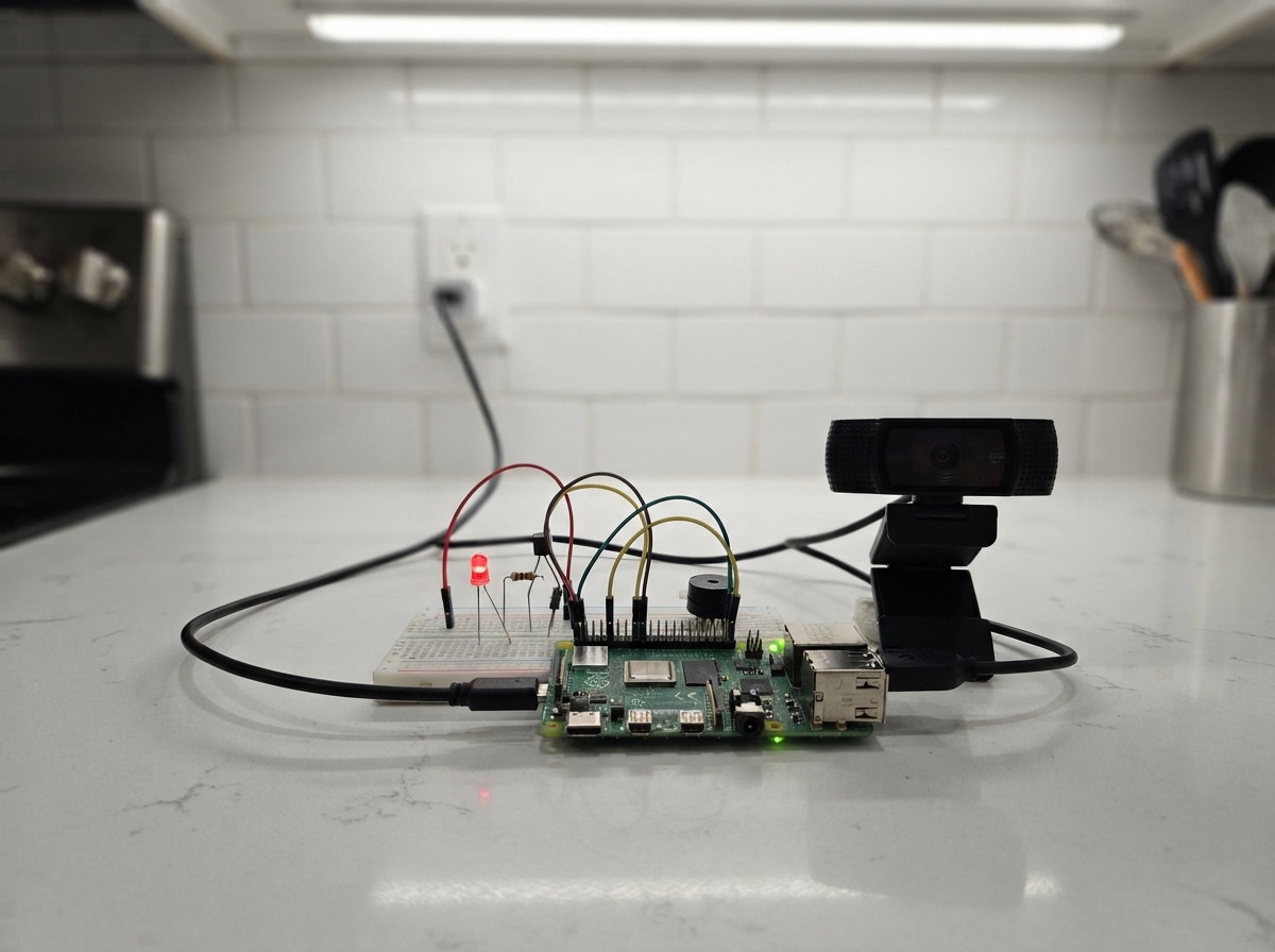
This IoT PPE Compliance Monitor uses an ESP32 microcontroller to receive real-time safety status updates from a Raspberry Pi 4 over WiFi and MQTT, displaying compliance state through LED indicators and an audio alarm. The system connects to a networked camera system that monitors PPE usage, translating detection results into immediate visual and audible feedback on the shop floor or work site.
The guide provides a complete wiring diagram showing how to connect the status LEDs, buzzer circuit with transistor switching, and power distribution, along with a full parts list, the Arduino firmware for the ESP32, and step-by-step assembly instructions. Builders will learn how to set up MQTT communication between the Pi and ESP32, configure WiFi credentials, and test the safety state transitions from a remote monitoring application.
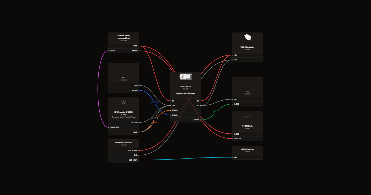
Wiring diagram
Gather all the parts
Assemble it in 4 steps
1. Connect the two indicator lights
Connect GPIO25 through its own 220-ohm resistor to the red LED long leg. Connect GPIO26 through the other 220-ohm resistor to the green LED long leg. Connect both short legs to ESP32 GND.
2. Build the buzzer switch
Connect GPIO23 through 1k ohm to the transistor base. Connect 10k ohm between base and ground. Connect emitter to ground and collector to buzzer minus. Connect buzzer plus to regulated 5V. Put the diode across the buzzer, banded cathode to plus and anode to minus.
- Check the exact 2N2222 package datasheet for base, collector and emitter; lead order varies. Use a 5V active buzzer rated at no more than 20mA. Never wire the buzzer directly to GPIO23.
3. Connect regulated power
Use an enclosed regulated 5V 4A supply with suitable separate leads. Feed Pi power through its USB-C connector, ESP32 through its 5V input, and buzzer through the 5V rail. Connect supply negative to ESP32 ground and Pi power ground. The supply must maintain 5V under computer and camera load.
- Unplug external ESP32 5V power before connecting PC USB for Deploy to prevent backfeeding. Do not connect 5V to 3V3 or any GPIO. Do not handle mains wiring.
4. Connect the only sensor
Plug the Linux-compatible USB webcam into a Pi USB host socket. Aim it at the monitored work area. Pi and ESP32 communicate over the local network, not GPIO wires.
- This is an advisory prototype, not a certified safety interlock. Occlusion and missed people can cause incorrect results; keep independent workplace safety procedures.
Review all connections
1. Connections between "rred" and "ESP32"
2. Connections between "red" and "ESP32"
3. Connections between "rgreen" and "ESP32"
4. Connections between "green" and "ESP32"
5. Connections between "rbase" and "ESP32"
6. Connections between "rpulldown" and "ESP32"
7. Connections between "transistor" and "ESP32"
8. Connections between "buzzer" and "ESP32"
9. Connections between "diode" and "ESP32"
10. Connections between "supply" and "ESP32"
11. Connections between "pi" and "ESP32"
12. Connections between "webcam" and "ESP32"
Deploy the firmware
#include <Arduino.h>
#include <WiFi.h>
#include <PubSubClient.h>
// Edit these settings before Deploy. Use the Pi's reserved LAN address.
const char* WIFI_SSID = "YOUR_WIFI_NAME";
const char* WIFI_PASSWORD = "YOUR_WIFI_PASSWORD";
const char* MQTT_HOST = "192.168.1.100";
const char* MQTT_USER = "ppe";
const char* MQTT_PASSWORD = "CHANGE_ME";
constexpr uint8_t RED_PIN=25, GREEN_PIN=26, BUZZER_PIN=23;
constexpr uint32_t DATA_TIMEOUT_MS=3500;
WiFiClient transport;
PubSubClient mqtt(transport);
enum class State { SAFE, UNSAFE, EMPTY, UNKNOWN };
State result=State::UNKNOWN;
bool received=false;
uint32_t lastData=0, lastAttempt=0, lastWifiAttempt=0;
String clientId;
void outputs() {
  const uint32_t now=millis();
  State effective=(WiFi.status()==WL_CONNECTED && mqtt.connected() && received &&
    uint32_t(now-lastData)<DATA_TIMEOUT_MS) ? result : State::UNKNOWN;
  digitalWrite(GREEN_PIN, effective==State::SAFE);
  digitalWrite(BUZZER_PIN, effective==State::UNSAFE);
  digitalWrite(RED_PIN, effective==State::UNSAFE ||
    (effective==State::UNKNOWN && ((now/500)%2==0)));
}
void message(char* topic, byte* payload, unsigned int length) {
  if (strcmp(topic,"safety/ppe")!=0) return;
  // Exact uppercase plain-text messages only; malformed data clears SAFE.
  String text;
  if (length<=7) for (unsigned int i=0;i<length;i++) text+=char(payload[i]);
  if(text=="SAFE") result=State::SAFE;
  else if(text=="UNSAFE") result=State::UNSAFE;
  else if(text=="EMPTY") result=State::EMPTY;
  else result=State::UNKNOWN;
  received=true;
  lastData=millis();
  outputs();
}
void setup() {
  digitalWrite(RED_PIN,LOW); digitalWrite(GREEN_PIN,LOW); digitalWrite(BUZZER_PIN,LOW);
  pinMode(RED_PIN,OUTPUT); pinMode(GREEN_PIN,OUTPUT); pinMode(BUZZER_PIN,OUTPUT);
  Serial.begin(115200);
  WiFi.mode(WIFI_STA); WiFi.begin(WIFI_SSID,WIFI_PASSWORD);
  mqtt.setServer(MQTT_HOST,1883); mqtt.setCallback(message);
  mqtt.setSocketTimeout(1); mqtt.setKeepAlive(10);
  clientId="ppe-actuator-"+String((uint32_t)ESP.getEfuseMac(),HEX);
  outputs();
}
void loop() {
  uint32_t now=millis();
  outputs();
  if(WiFi.status()!=WL_CONNECTED) {
    received=false;
    if(mqtt.connected()) mqtt.disconnect();
    if(uint32_t(now-lastWifiAttempt)>=10000) {
      lastWifiAttempt=now; WiFi.reconnect();
    }
  } else if(!mqtt.connected()) {
    received=false;
    if(uint32_t(now-lastAttempt)>=3000) {
      lastAttempt=now;
      // Connection attempts happen with outputs already in UNKNOWN state.
      if(mqtt.connect(clientId.c_str(),MQTT_USER,MQTT_PASSWORD)) {
        if(!mqtt.subscribe("safety/ppe",0)) mqtt.disconnect();
        Serial.println("MQTT connected; waiting for fresh PPE data");
      }
    }
  } else mqtt.loop();
  outputs();
  delay(5);
}
Remix this project
Make it yours in one click
Open a full copy of this project in your own Schematik workspace, diagram, code, parts, and assembly steps included. Swap the sensor, add features, or redesign the whole thing with AI. The author's original stays untouched.