Community project
Make Arduino Rotating Clock Using Led Line
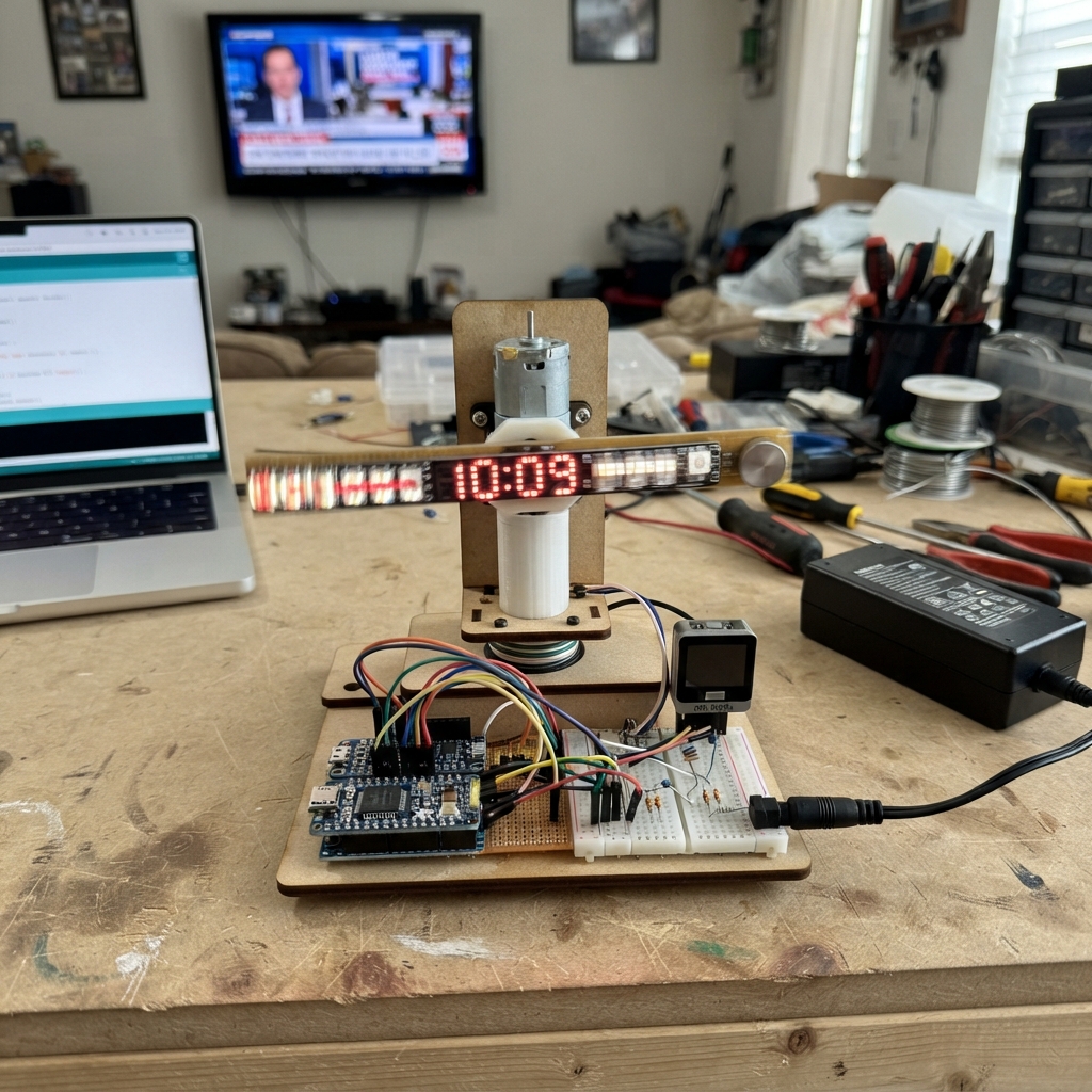
This project builds a mesmerizing analog clock that displays the time using a rotating arm of addressable LEDs. As the arm spins, the WS2812B LEDs light up in patterns that form digits, creating a persistence-of-vision display that shows hours and minutes. The rotation is driven by a geared DC motor and synchronized using a Hall effect sensor that detects a magnet on the spinning shaft, while a precision RTC module keeps accurate time.
Builders will receive a complete wiring diagram showing how to connect the motor, slip ring, LED strip, Hall sensor, and power supply to the Arduino Uno, along with a full parts list and firmware that handles the timing synchronization and LED animation. The assembly guide walks through constructing the rotating arm guard, mounting the motor and sensor, and calibrating the display so the time appears correctly as the arm sweeps around.
Wiring diagram

Gather all the parts
Assemble it in 5 steps
1. Make a guarded rotating arm
Fix the 8-pixel LED line (led_line) firmly to a light, balanced arm attached to the motor shaft. Put pixel 0 at the lower end and keep the LEDs facing outward. Glue the small magnet (magnet) to the arm so it passes the fixed Hall sensor once per revolution. Enclose the whole spinning arm in a clear guard before powering the motor.
- Turn the shaft by hand first: the arm must not wobble or touch the guard.
- Keep the magnet 2 to 5 mm from the sensor face; flip the magnet if the sensor’s small indicator light does not react.
- An unguarded spinning arm can strike fingers, snag hair, or throw loose parts across the room.
2. Wire the fixed clock and rotation marker
With power unplugged, connect the RTC module (rtc): VIN → 5V (power), GND → GND (ground), SDA → Arduino A4 / GPIO18 (data), and SCL → Arduino A5 / GPIO19 (clock). Connect the Hall sensor (hall_sensor): 5V → 5V (power), GND → GND (ground), and OUT → Arduino D2 / GPIO2 (rotation signal).
- Fit a CR1220 backup cell in the RTC holder if your module has one; it keeps the time while the main supply is unplugged.
- All GND connections must join together so the Arduino can read the sensor reliably.
- Make sure 5V and GND are not swapped — swapped power can damage the modules.
3. Wire the rotating LED arm
Connect Arduino D6 / GPIO6 to one end of the 330 Ω resistor (data_resistor); connect its other end to the fixed-side DATA wire on the slip ring (slip_ring). Connect the slip ring’s fixed-side 5V → 5V (power) and fixed-side GND → GND (ground). On the rotating side, connect 5V rotor → LED line VCC (power), GND rotor → LED line GND (ground), and DATA rotor → LED line DATA (signal). Put the capacitor (supply_capacitor) across the LED line: + → VCC (power) and the striped − lead → GND (ground).
- Use flexible, strain-relieved wires on the rotating side so they cannot rub the shaft.
- The resistor is installed in the data wire, not across the 5V and GND wires.
- The capacitor’s striped negative lead must go to GND; reversing it can make it hot or burst.
4. Connect the motor and supply
Connect the regulated 5V supply (power_supply) 5V+ → the shared 5V rail (power) and GND → the shared GND rail (ground). Connect motor M+ → 5V (power) and M− → GND (ground). Power the Arduino from the same regulated 5V rail through its 5V pin, not through VIN.
- Use a 5V supply rated for at least 3 A, and keep the motor leads twisted together where practical to reduce electrical noise.
- Check the arm is inside its guard before applying power.
- Do not connect a 5V supply to the Arduino VIN pin — VIN expects a higher input voltage and the board may behave unreliably. Never work on wiring while the wall supply is plugged in.
5. Set the time and check the image
After the design is deployed, the RTC will set itself once from the firmware build time if its backup cell was flat or missing. Watch the guarded arm from the side: the blue HH:MM time should appear still in the air. If the digits are upside down, reverse the LED strip physically or change the indicated pixel order in the firmware.
- The motor should run near 600 RPM; if the image drifts or smears, adjust the magnet gap and make sure it gives exactly one clean sensor trigger per turn.
- Stop power before repositioning the magnet, sensor, LED arm, or guard.
Review all connections
1. Connections between "power_supply" and "Arduino"
2. Connections between "rtc" and "Arduino"
3. Connections between "hall_sensor" and "Arduino"
4. Connections between "data_resistor" and "Arduino"
5. Connections between "slip_ring" and "Arduino"
6. Connections between "supply_capacitor" and "Arduino"
7. Connections between "motor" and "Arduino"
Deploy the firmware
#include <Arduino.h>
#include <Wire.h>
#include <RTClib.h>
#include <Adafruit_NeoPixel.h>

// Forward declarations
void onMarker();
bool pixelForColumn(const uint8_t column, const uint8_t y, const uint8_t values[4]);
void showColumn(uint8_t phaseColumn);

constexpr uint8_t HALL_PIN = 2;
constexpr uint8_t LED_DATA_PIN = 6;
constexpr uint8_t LED_COUNT = 8; // Number of LEDs on the rotating arm, not a board pin.
constexpr uint8_t COLUMNS_PER_TURN = 120;
constexpr uint8_t GLYPH_HEIGHT = 5;
constexpr uint8_t DISPLAY_Y_OFFSET = 1;
constexpr uint8_t BRIGHTNESS = 32;

Adafruit_NeoPixel leds(LED_COUNT, LED_DATA_PIN, NEO_GRB + NEO_KHZ800);
RTC_DS3231 rtc;

volatile uint32_t markerMicros = 0;
volatile uint32_t previousMarkerMicros = 0;
volatile uint32_t revolutionMicros = 100000;
volatile bool markerSeen = false;

uint8_t lastColumn = 255;

const uint8_t digits[10][GLYPH_HEIGHT] = {
  {0b111, 0b101, 0b101, 0b101, 0b111},
  {0b010, 0b110, 0b010, 0b010, 0b111},
  {0b111, 0b001, 0b111, 0b100, 0b111},
  {0b111, 0b001, 0b111, 0b001, 0b111},
  {0b101, 0b101, 0b111, 0b001, 0b001},
  {0b111, 0b100, 0b111, 0b001, 0b111},
  {0b111, 0b100, 0b111, 0b101, 0b111},
  {0b111, 0b001, 0b010, 0b010, 0b010},
  {0b111, 0b101, 0b111, 0b101, 0b111},
  {0b111, 0b101, 0b111, 0b001, 0b111}
};

void onMarker() {
  const uint32_t now = micros();
  const uint32_t interval = now - markerMicros;
  // Ignore a second trigger from the same magnet pass and unreasonable speeds.
  if (interval > 20000UL && interval < 500000UL) {
    previousMarkerMicros = markerMicros;
    markerMicros = now;
    revolutionMicros = interval;
    markerSeen = true;
  } else if (markerMicros == 0) {
    markerMicros = now;
    markerSeen = true;
  }
}

bool pixelForColumn(const uint8_t column, const uint8_t y, const uint8_t values[4]) {
  // Each digit is 3 columns wide. The two separator dots occupy one column.
  uint8_t cursor = 0;
  for (uint8_t digitIndex = 0; digitIndex < 4; ++digitIndex) {
    if (digitIndex == 2) {
      if (column == cursor && (y == 1 || y == 3)) return true;
      ++cursor;
    }
    if (column >= cursor && column < cursor + 3) {
      const uint8_t bit = 2 - (column - cursor);
      return (digits[values[digitIndex]][y] & (1 << bit)) != 0;
    }
    cursor += 3;
    if (digitIndex != 3) ++cursor;
  }
  return false;
}

void showColumn(uint8_t phaseColumn) {
  // Put the 15-column HH:MM image in the middle of a 120-column turn.
  const int16_t imageColumn = static_cast<int16_t>(phaseColumn) - 52;
  leds.clear();

  if (imageColumn >= 0 && imageColumn < 15) {
    const DateTime now = rtc.now();
    const uint8_t values[4] = {
      static_cast<uint8_t>(now.hour() / 10),
      static_cast<uint8_t>(now.hour() % 10),
      static_cast<uint8_t>(now.minute() / 10),
      static_cast<uint8_t>(now.minute() % 10)
    };

    for (uint8_t y = 0; y < GLYPH_HEIGHT; ++y) {
      if (pixelForColumn(static_cast<uint8_t>(imageColumn), y, values)) {
        // Reverse if your physical strip is fitted with pixel 0 at the top.
        leds.setPixelColor(DISPLAY_Y_OFFSET + y, leds.Color(0, 0, BRIGHTNESS));
      }
    }
  }
  leds.show();
}

void setup() {
  pinMode(HALL_PIN, INPUT_PULLUP);
  attachInterrupt(digitalPinToInterrupt(HALL_PIN), onMarker, FALLING);

  Wire.begin();
  rtc.begin();
  if (rtc.lostPower()) {
    // Sets the RTC once from the firmware build time after a flat or missing coin cell.
    rtc.adjust(DateTime(__DATE__, __TIME__));
  }

  leds.begin();
  leds.setBrightness(BRIGHTNESS);
  leds.clear();
  leds.show();
}

void loop() {
  uint32_t markerCopy;
  uint32_t revolutionCopy;
  bool seenCopy;
  noInterrupts();
  markerCopy = markerMicros;
  revolutionCopy = revolutionMicros;
  seenCopy = markerSeen;
  interrupts();

  if (!seenCopy || revolutionCopy == 0) {
    return;
  }

  const uint32_t elapsed = micros() - markerCopy;
  if (elapsed >= revolutionCopy) {
    return; // Wait for the next Hall marker rather than drawing with a guessed angle.
  }

  const uint8_t column = static_cast<uint8_t>((elapsed * COLUMNS_PER_TURN) / revolutionCopy);
  if (column != lastColumn) {
    lastColumn = column;
    showColumn(column);
  }
}
Remix this project
Make it yours in one click
Open a full copy of this project in your own Schematik workspace — diagram, code, parts, and assembly steps included. Swap the sensor, add features, or redesign the whole thing with AI. The author's original stays untouched.
Related projects
Soldering Stand with Fume Extractor and Lighting
Arduino · September 22, 2026prahaladh.pradeep
Multisensor Home Safety Alert System
Arduino · September 22, 2026SHIVΞSH
Smart Gait Analysis Platform
Arduino · September 22, 2026jose amorim