Community project
Manhole Hazard Monitoring System
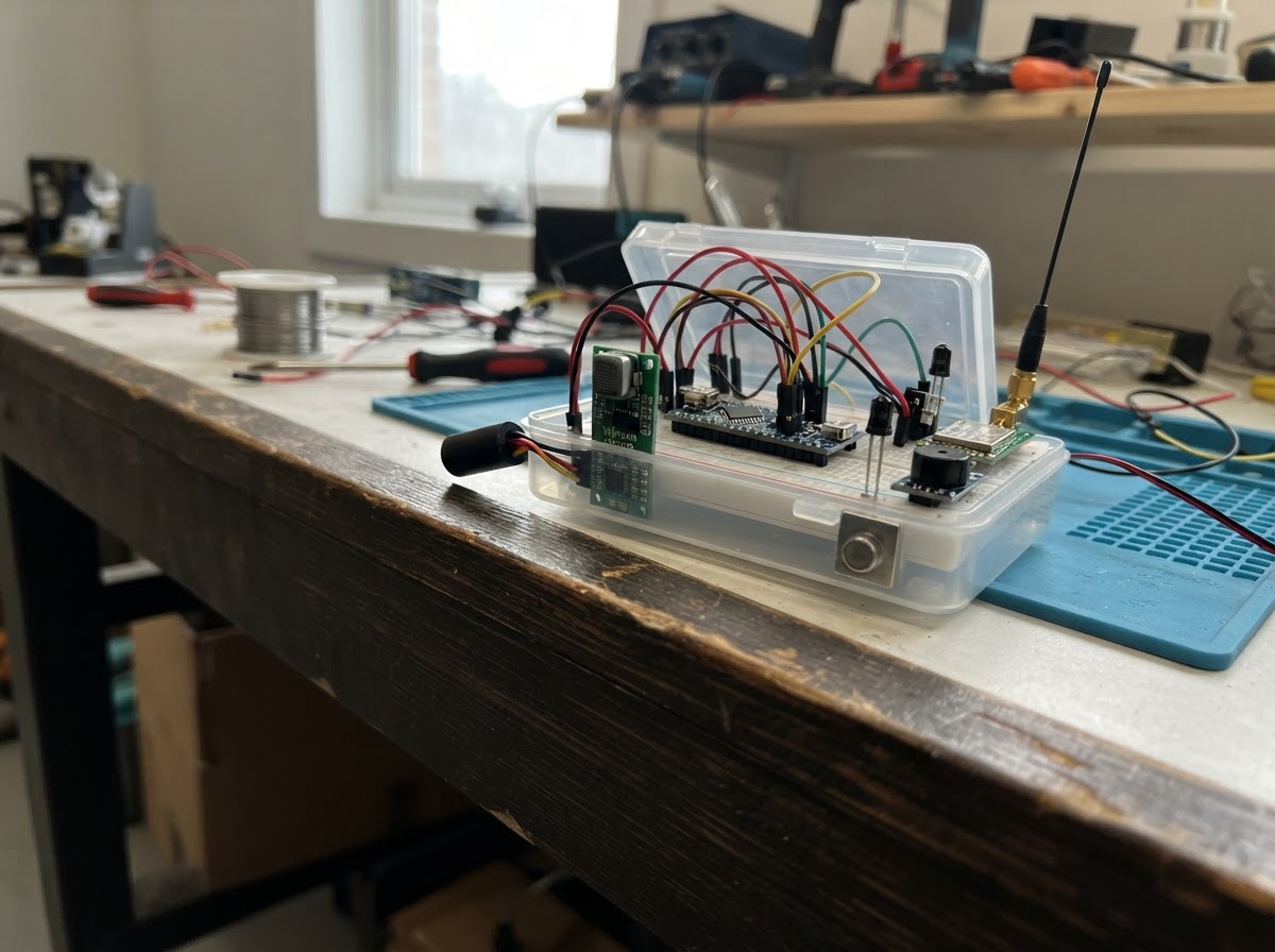
This project builds a remote monitoring system for manhole safety using an ESP32 microcontroller to detect hazardous gases, water ingress, unauthorized access, and rodent activity. The system combines a Winsen ZCE04B four-gas sensor, float switch, reed switch, infrared beam pair, and piezo buzzer to monitor conditions locally while transmitting alerts over LoRaWAN via an SX1262 radio module.
The guide provides a complete parts list, wiring diagram showing all sensor and radio connections, step-by-step assembly instructions for weatherproofing the electronics enclosure, and Arduino firmware with LoRaWAN OTAA join logic. Builders will learn how to configure network credentials, parse UART gas data, debounce digital inputs, trigger local alarms, and send status packets to a LoRaWAN network for remote monitoring.
Wiring diagram

Gather all the parts
Assemble it in 8 steps
1. Keep the electronics dry
Put the ESP32, LoRaWAN radio, buzzer, and gas-monitor circuit board in a weatherproof enclosure above the highest possible water line. Use cable glands for every cable so water cannot run down a wire into the box.
- Keep the radio antenna outside the metal cover and enclosure, or use a sealed antenna lead to a mounting point with a clear path toward the gateway.
- Do not place ordinary electronics or a non-certified radio in a potentially explosive gas space; use certified equipment and installation practices where required.
2. Wire the gas monitor
With all power unplugged, join the gas monitor VCC to the ESP32 3V3 pin (power), GND to an ESP32 GND pin (ground), TX to GPIO16 (gas-reading data), and RX to GPIO17 (gas-monitor command data).
- Use the actual ZCE04B variant confirmed to work at 3.3 V UART levels; do not connect a 5 V serial output directly to the ESP32.
- A gas monitor is a safety device: calibrate and maintain it exactly as its manufacturer specifies, and never use this DIY node as the only protection for people entering a manhole.
3. Install the water switch
Mount the IP68 float switch at the water height that should create an alarm. Connect its GND wire to ESP32 GND (ground) and its SIGNAL wire to GPIO26 (water-warning signal). Set the float orientation so its normally-closed contacts are closed while the water is below the alarm level.
- The code treats an open contact or broken wire as a water alarm, which is safer than silently ignoring a damaged cable.
- Make sure the float can move freely; trapped debris can stop it from reporting rising water.
4. Fit the cover tamper switch
Fix the sealed reed switch to the fixed rim and its magnet to the underside of the cover so the magnet holds the switch closed when the cover is seated. Connect PIN1 to GPIO27 (cover-movement signal) and PIN2 to ESP32 GND (ground).
- Test the spacing before sealing it: lifting the cover or moving the magnet away should create the tamper alarm.
- Keep the switch and magnet clear of pinch points so a moving cover cannot cut their cable.
5. Place the rodent light beam
Mount the infrared transmitter and receiver facing each other across a narrow route where an animal must pass. Connect VCC to 3V3 (power), GND to GND (ground), and OUT to GPIO32 (rodent-crossing signal).
- Use a short protected path because this low-voltage beam is intended for about 20–25 cm at 3.3 V. Aim it before permanently fastening it.
- This small beam pair is not waterproof; install it behind a clear protected window or replace it with an equivalently wired IP-rated beam sensor.
6. Wire the LoRaWAN radio
Connect the SX1262 VCC to ESP32 3V3 (power), GND to ESP32 GND (ground), SCK to GPIO18 (clock), MISO to GPIO19 (radio data), MOSI to GPIO23 (radio data), NSS to GPIO4 (radio select), DIO1 to GPIO33 (radio-ready signal), NRST to GPIO13 (radio reset), and BUSY to GPIO14 (radio-busy signal). Attach the matching Singapore AS923 antenna before powering the radio.
- One gateway can serve many manholes when radio coverage reaches them; add gateways or outdoor antennas for weak underground coverage rather than expecting one manhole node to relay another node's message.
- Do not transmit without the correct antenna attached — transmitting with no antenna can damage the radio. Use only a radio and antenna approved for the Singapore 920–925 MHz band.
7. Wire the local warning sounder
Connect the buzzer VCC to 3V3 (power), GND to GND (ground), and SIG to GPIO25 (warning-sound control).
- The buzzer sounds for water, cover, or gas alarms even when the LoRaWAN gateway cannot be reached.
- Use only a 3.3 V active buzzer module here; a higher-voltage sounder can damage the ESP32 output or fail to sound.
8. Add the network identity and test safely
Before deployment, enter this node's four OTAA credentials from your LoRaWAN network in the firmware. Plug the ESP32 into USB at a safe work area, check that the wiring matches the diagram, and test each switch by hand. After it behaves correctly, close the enclosure and secure all cables.
- The device sends one compact LoRaWAN report every five minutes, with water, cover, and gas alarm flags plus the rodent-crossing count.
- Never enter a manhole to test this device. Poisonous gases and low oxygen can seriously injure or kill; use trained personnel and approved confined-space procedures.
Review all connections
1. Connections between "gas_monitor" and "ESP32"
2. Connections between "float_switch" and "ESP32"
3. Connections between "cover_reed" and "ESP32"
4. Connections between "rodent_beam" and "ESP32"
5. Connections between "buzzer" and "ESP32"
6. Connections between "lorawan_radio" and "ESP32"
Deploy the firmware
#include <Arduino.h>
#include <SPI.h>
#include <RadioLib.h>

// Enter the OTAA credentials issued for this individual node by your LoRaWAN server.
// Each value is hexadecimal text without spaces. Do not reuse device credentials.

// Forward declarations
void inspectGasLine(const String &line);
void readGasMonitor();
void updateInputs();
void sendStatus();

// Replace these zero placeholders with the hexadecimal OTAA values assigned to this node.
// RadioLib expects EUIs as 64-bit values and keys as 16 raw bytes.
const uint64_t JOIN_EUI = 0x0000000000000000ULL;
const uint64_t DEV_EUI  = 0x0000000000000000ULL;
const uint8_t NWK_KEY[16] = {0x00, 0x00, 0x00, 0x00, 0x00, 0x00, 0x00, 0x00,
                             0x00, 0x00, 0x00, 0x00, 0x00, 0x00, 0x00, 0x00};
const uint8_t APP_KEY[16] = {0x00, 0x00, 0x00, 0x00, 0x00, 0x00, 0x00, 0x00,
                             0x00, 0x00, 0x00, 0x00, 0x00, 0x00, 0x00, 0x00};

constexpr int GAS_RX_PIN = 16;
constexpr int GAS_TX_PIN = 17;
constexpr int WATER_PIN = 26;
constexpr int COVER_PIN = 27;
constexpr int RODENT_PIN = 32;
constexpr int BUZZER_PIN = 25;
constexpr int LORA_SCK_PIN = 18;
constexpr int LORA_MISO_PIN = 19;
constexpr int LORA_MOSI_PIN = 23;
constexpr int LORA_NSS_PIN = 4;
constexpr int LORA_DIO1_PIN = 33;
constexpr int LORA_RESET_PIN = 13;
constexpr int LORA_BUSY_PIN = 14;

constexpr uint8_t LORAWAN_PORT = 10;
constexpr unsigned long REPORT_INTERVAL_MS = 300000UL;
constexpr unsigned long DEBOUNCE_MS = 60;

HardwareSerial gasSerial(2);
SX1262 radio = new Module(LORA_NSS_PIN, LORA_DIO1_PIN, LORA_RESET_PIN, LORA_BUSY_PIN);
LoRaWANNode node(&radio, &AS923);

bool waterAlarm = false;
bool coverAlarm = false;
bool gasAlarm = false;
bool lorawanJoined = false;
uint32_t rodentCount = 0;
int lastRodentRaw = HIGH;
unsigned long lastRodentEdgeMs = 0;
unsigned long lastReportMs = 0;
String gasLine;

void inspectGasLine(const String &line) {
  String upper = line;
  upper.toUpperCase();
  // The gas monitor itself must have its alarm thresholds configured by qualified staff.
  gasAlarm = upper.indexOf("ALARM") >= 0 || upper.indexOf("FAULT") >= 0;
}

void readGasMonitor() {
  while (gasSerial.available()) {
    char c = static_cast<char>(gasSerial.read());
    if (c == '\n' || c == '\r') {
      if (gasLine.length() > 0) {
        inspectGasLine(gasLine);
        gasLine = "";
      }
    } else if (gasLine.length() < 120) {
      gasLine += c;
    }
  }
}

void updateInputs() {
  // Normally-closed circuits: an open contact or cut cable becomes an alarm.
  waterAlarm = digitalRead(WATER_PIN) == HIGH;
  coverAlarm = digitalRead(COVER_PIN) == HIGH;

  int rodentRaw = digitalRead(RODENT_PIN);
  if (lastRodentRaw == HIGH && rodentRaw == LOW && millis() - lastRodentEdgeMs > DEBOUNCE_MS) {
    ++rodentCount;
    lastRodentEdgeMs = millis();
  }
  lastRodentRaw = rodentRaw;

  digitalWrite(BUZZER_PIN, (waterAlarm || coverAlarm || gasAlarm) ? HIGH : LOW);
}

void sendStatus() {
  // Compact LoRaWAN payload: flags, 16-bit rodent count, and joined-state marker.
  uint8_t payload[4];
  payload[0] = (waterAlarm ? 0x01 : 0x00) |
               (coverAlarm ? 0x02 : 0x00) |
               (gasAlarm ? 0x04 : 0x00);
  payload[1] = static_cast<uint8_t>((rodentCount >> 8) & 0xFF);
  payload[2] = static_cast<uint8_t>(rodentCount & 0xFF);
  payload[3] = 1;

  if (!lorawanJoined) {
    Serial.println("LoRaWAN not joined; status retained for next report.");
    return;
  }

  // sendReceive also listens during LoRaWAN receive windows for network commands.
  uint8_t downlink[32];
  size_t downlinkLength = 0;
  int state = node.sendReceive(payload, sizeof(payload), LORAWAN_PORT,
                               downlink, &downlinkLength);
  if (state >= RADIOLIB_ERR_NONE) {
    Serial.println("LoRaWAN status sent.");
  } else {
    Serial.printf("LoRaWAN uplink failed: %d\n", state);
  }
}

void setup() {
  Serial.begin(115200);
  gasSerial.begin(9600, SERIAL_8N1, GAS_RX_PIN, GAS_TX_PIN);
  pinMode(WATER_PIN, INPUT_PULLUP);
  pinMode(COVER_PIN, INPUT_PULLUP);
  pinMode(RODENT_PIN, INPUT_PULLUP);
  pinMode(BUZZER_PIN, OUTPUT);
  digitalWrite(BUZZER_PIN, LOW);

  SPI.begin(LORA_SCK_PIN, LORA_MISO_PIN, LORA_MOSI_PIN, LORA_NSS_PIN);
  int state = radio.begin();
  if (state != RADIOLIB_ERR_NONE) {
    Serial.printf("SX1262 startup failed: %d\n", state);
    return;
  }

  node.beginOTAA(JOIN_EUI, DEV_EUI, NWK_KEY, APP_KEY);
  state = node.activateOTAA();
  lorawanJoined = (state == RADIOLIB_LORAWAN_NEW_SESSION || state == RADIOLIB_LORAWAN_SESSION_RESTORED);
  if (lorawanJoined) {
    Serial.println("Joined Singapore AS923 LoRaWAN network.");
  } else {
    Serial.printf("LoRaWAN join failed: %d\n", state);
  }
  sendStatus();
}

void loop() {
  readGasMonitor();
  updateInputs();

  if (millis() - lastReportMs >= REPORT_INTERVAL_MS) {
    lastReportMs = millis();
    sendStatus();
  }
}
Remix this project
Make it yours in one click
Open a full copy of this project in your own Schematik workspace — diagram, code, parts, and assembly steps included. Swap the sensor, add features, or redesign the whole thing with AI. The author's original stays untouched.