Community project
Manual Fan Temperature Control
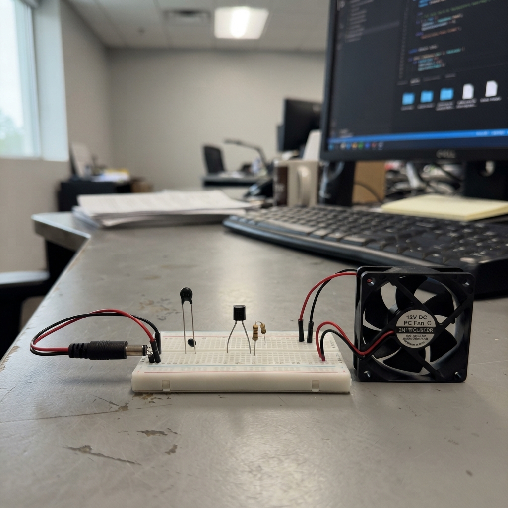
This project builds a smart temperature-controlled fan system using an ESP32 S3 to monitor ambient conditions and automatically adjust cooling. The system reads temperature data from an NTC thermistor and drives up to three PC fans via PWM-controlled transistor circuits, powered by a 12V supply. The built-in RGB status LED provides real-time feedback on system state, WiFi connectivity, and API connection status.
This guide provides a complete wiring diagram, parts list, and step-by-step assembly instructions for connecting the thermistor sensor, transistor fan drivers, and 12V power distribution. The included ESPHome firmware handles temperature sensing, fan speed modulation, and network connectivity, allowing remote monitoring and control through Home Assistant or other compatible platforms.
Wiring diagram

Gather all the parts
Assemble it in 6 steps
1. Set up the 12 V fan supply
With power unplugged, connect the 12 V adapter positive lead to the red 12 V wire of fan_1, fan_2, and fan_3. Connect the adapter negative lead to every fan black ground wire and to an ESP32 GND pin. This shared ground lets the board safely control the fans and read their speed.
- The usual four-wire fan colors are red 12 V, black GND, blue PWM, and yellow TACH, but read the label on your fans because colors can vary.
- Do not connect the 12 V adapter to the ESP32 board — 12 V can permanently damage it.
2. Make the five temperature connections
For each NTC probe, connect its SIG wire to GPIO1, GPIO2, GPIO3, GPIO4, or GPIO5 respectively. Connect each probe VCC wire to 3V3 and each GND wire to GND. For each matching 10 kΩ resistor, connect one leg to 3V3 and the other leg to that probe's SIG/GPIO junction; the probe and resistor together measure temperature.
- Keep each resistor and its matching probe together so the temperature names remain correct in the ESPHome sidebar.
- Do not connect an NTC signal wire to 5 V — the ESP32 inputs use 3.3 V only and higher voltage can damage the board.
3. Add the three fan control transistors
For each 2N3904, connect the emitter to the shared GND and collector to its matching fan PWM wire. Connect GPIO38, GPIO39, or GPIO40 through its matching 4.7 kΩ resistor to that transistor base. Check the flat face and lead order against the marking for your exact 2N3904 part before soldering; the driver pulls the fan control wire low without sending 12 V into the ESP32.
- Keep the blue PWM control wires separate from the red 12 V wires.
- A transistor with emitter and collector swapped may prevent the fan speed control from working.
4. Connect the fan speed wires
Connect fan_1 TACH to GPIO17, fan_2 TACH to GPIO18, and fan_3 TACH to GPIO47. For each speed wire, connect one 10 kΩ resistor leg to 3V3 and the other resistor leg to the same TACH/GPIO junction. These resistors let the board count the fan speed pulses.
- The TACH wire is only a speed signal; it does not power the fan.
- Do not pull a TACH wire up to 5 V — its GPIO connection must stay at the ESP32-safe 3.3 V level.
5. Use the built-in status light
Do not add any external RGB LED, level shifter, or 5 V LED wiring. The ESP32-S3-Zero already has its own RGB status light inside the board, controlled by GPIO16.
- GPIO16 is used only by the built-in status light, so leave it unconnected on your external wiring.
- Do not attach another device to GPIO16 — it could interfere with the board's built-in status light.
6. Power and control the system
First power the ESP32-S3-Zero through its USB-C connector. Then plug in the 12 V fan supply. After deployment, use the three Fan controls in the ESPHome dashboard sidebar to set each fan speed, and use the Built-in Status RGB LED control to choose the board light's color.
- Keep the USB and 12 V grounds connected together; without a shared ground, the fan controls and speed readings can behave unpredictably.
- Turn off the 12 V supply before moving any fan or transistor wires.
Review all connections
1. Connections between "supply_12v" and "ESP32"
2. Connections between "fan_1" and "ESP32"
3. Connections between "fan_2" and "ESP32"
4. Connections between "fan_3" and "ESP32"
5. Connections between "ntc_1" and "ESP32"
6. Connections between "ntc_2" and "ESP32"
7. Connections between "ntc_3" and "ESP32"
8. Connections between "ntc_4" and "ESP32"
9. Connections between "ntc_5" and "ESP32"
10. Connections between "ntc_resistor_1" and "ESP32"
11. Connections between "ntc_resistor_2" and "ESP32"
12. Connections between "ntc_resistor_3" and "ESP32"
13. Connections between "ntc_resistor_4" and "ESP32"
14. Connections between "ntc_resistor_5" and "ESP32"
15. Connections between "pwm_base_resistor_1" and "ESP32"
16. Connections between "fan_pwm_driver_1" and "ESP32"
17. Connections between "pwm_base_resistor_2" and "ESP32"
18. Connections between "fan_pwm_driver_2" and "ESP32"
19. Connections between "pwm_base_resistor_3" and "ESP32"
20. Connections between "fan_pwm_driver_3" and "ESP32"
21. Connections between "tach_pullup_1" and "ESP32"
22. Connections between "tach_pullup_2" and "ESP32"
23. Connections between "tach_pullup_3" and "ESP32"
Deploy the firmware
esphome:
  name: s3zero-fanctl-v2
  friendly_name: S3 Zero Environment Controller
  on_boot:
    priority: -100
    then:
      - light.turn_on:
          id: status_led
          red: 100%
          green: 0%
          blue: 0%
          brightness: 35%
esp32:
  variant: esp32s3
  framework:
    type: arduino

logger:

api:
  on_client_connected:
    then:
      - light.turn_on:
          id: status_led
          red: 0%
          green: 100%
          blue: 0%
          brightness: 35%
  on_client_disconnected:
    then:
      - light.turn_on:
          id: status_led
          red: 100%
          green: 0%
          blue: 0%
          brightness: 35%

ota:
  - platform: esphome

wifi:
  on_connect:
    then:
      - light.turn_on:
          id: status_led
          red: 100%
          green: 0%
          blue: 0%
          brightness: 35%
  on_disconnect:
    then:
      - light.turn_on:
          id: status_led
          red: 100%
          green: 75%
          blue: 0%
          brightness: 35%
  ap:
    ssid: "S3-Zero Fan Control"
    password: "fancontrol2026"

captive_portal:

output:
  - platform: ledc
    pin:
      number: GPIO38
      inverted: true
    id: fan_1_pwm
    frequency: 25000 Hz
  - platform: ledc
    pin:
      number: GPIO39
      inverted: true
    id: fan_2_pwm
    frequency: 25000 Hz
  - platform: ledc
    pin:
      number: GPIO40
      inverted: true
    id: fan_3_pwm
    frequency: 25000 Hz

fan:
  - platform: speed
    output: fan_1_pwm
    name: "Fan 1"
    speed_count: 100
  - platform: speed
    output: fan_2_pwm
    name: "Fan 2"
    speed_count: 100
  - platform: speed
    output: fan_3_pwm
    name: "Fan 3"
    speed_count: 100

light:
  - platform: esp32_rmt_led_strip
    rgb_order: GRB
    chipset: WS2812
    pin: GPIO16
    num_leds: 1
    id: status_led
    name: "Built-in Status RGB LED"
    restore_mode: RESTORE_DEFAULT_OFF

sensor:
  - platform: adc
    pin: GPIO1
    id: ntc_1_voltage
    attenuation: auto
    update_interval: 10s
  - platform: resistance
    sensor: ntc_1_voltage
    id: ntc_1_resistance
    configuration: DOWNSTREAM
    resistor: 10kOhm
  - platform: ntc
    sensor: ntc_1_resistance
    calibration:
      b_constant: 3590
      reference_temperature: 25°C
      reference_resistance: 10kOhm
    name: "Temperature 1"
    unit_of_measurement: "°C"
    accuracy_decimals: 1
    device_class: temperature
    state_class: measurement

  - platform: adc
    pin: GPIO2
    id: ntc_2_voltage
    attenuation: auto
    update_interval: 10s
  - platform: resistance
    sensor: ntc_2_voltage
    id: ntc_2_resistance
    configuration: DOWNSTREAM
    resistor: 10kOhm
  - platform: ntc
    sensor: ntc_2_resistance
    calibration:
      b_constant: 3590
      reference_temperature: 25°C
      reference_resistance: 10kOhm
    name: "Temperature 2"
    unit_of_measurement: "°C"
    accuracy_decimals: 1
    device_class: temperature
    state_class: measurement

  - platform: adc
    pin: GPIO3
    id: ntc_3_voltage
    attenuation: auto
    update_interval: 10s
  - platform: resistance
    sensor: ntc_3_voltage
    id: ntc_3_resistance
    configuration: DOWNSTREAM
    resistor: 10kOhm
  - platform: ntc
    sensor: ntc_3_resistance
    calibration:
      b_constant: 3590
      reference_temperature: 25°C
      reference_resistance: 10kOhm
    name: "Temperature 3"
    unit_of_measurement: "°C"
    accuracy_decimals: 1
    device_class: temperature
    state_class: measurement

  - platform: adc
    pin: GPIO4
    id: ntc_4_voltage
    attenuation: auto
    update_interval: 10s
  - platform: resistance
    sensor: ntc_4_voltage
    id: ntc_4_resistance
    configuration: DOWNSTREAM
    resistor: 10kOhm
  - platform: ntc
    sensor: ntc_4_resistance
    calibration:
      b_constant: 3590
      reference_temperature: 25°C
      reference_resistance: 10kOhm
    name: "Temperature 4"
    unit_of_measurement: "°C"
    accuracy_decimals: 1
    device_class: temperature
    state_class: measurement

  - platform: adc
    pin: GPIO5
    id: ntc_5_voltage
    attenuation: auto
    update_interval: 10s
  - platform: resistance
    sensor: ntc_5_voltage
    id: ntc_5_resistance
    configuration: DOWNSTREAM
    resistor: 10kOhm
  - platform: ntc
    sensor: ntc_5_resistance
    calibration:
      b_constant: 3590
      reference_temperature: 25°C
      reference_resistance: 10kOhm
    name: "Temperature 5"
    unit_of_measurement: "°C"
    accuracy_decimals: 1
    device_class: temperature
    state_class: measurement

  - platform: pulse_counter
    pin:
      number: GPIO17
      mode: INPUT
    name: "Fan 1 RPM"
    unit_of_measurement: "RPM"
    accuracy_decimals: 0
    state_class: measurement
    device_class: speed
    update_interval: 15s
    filters:
      - multiply: 0.5
  - platform: pulse_counter
    pin:
      number: GPIO18
      mode: INPUT
    name: "Fan 2 RPM"
    unit_of_measurement: "RPM"
    accuracy_decimals: 0
    state_class: measurement
    device_class: speed
    update_interval: 15s
    filters:
      - multiply: 0.5
  - platform: pulse_counter
    pin:
      number: GPIO47
      mode: INPUT
    name: "Fan 3 RPM"
    unit_of_measurement: "RPM"
    accuracy_decimals: 0
    state_class: measurement
    device_class: speed
    update_interval: 15s
    filters:
      - multiply: 0.5
Remix this project
Make it yours in one click
Open a full copy of this project in your own Schematik workspace — diagram, code, parts, and assembly steps included. Swap the sensor, add features, or redesign the whole thing with AI. The author's original stays untouched.