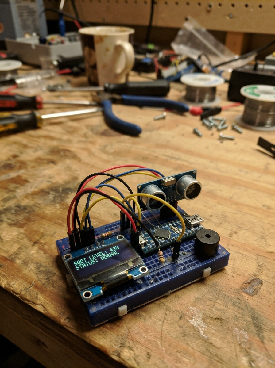
The Soot Trap Monitoring System tracks the fill level of a soot collection bin using an ultrasonic distance sensor and alerts when the trap is full. Built around an ESP32 microcontroller, the system displays real-time fill percentage on a small OLED screen and sounds a piezo buzzer alarm when the bin reaches capacity.
This guide provides a complete wiring diagram, parts list, and step-by-step assembly instructions to mount the distance sensor above the bin and connect all components to the ESP32. The included firmware handles distance measurement, fill calculation, display updates, and alarm triggering, making it ready to deploy as a maintenance alert system.
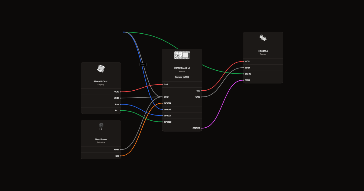
Wiring diagram
Gather all the parts
Assemble it in 4 steps
1. Connect the 0.96-inch 128x64 OLED with USB unplugged
Connect VCC to 3V3, GND to GND, SDA to GPIO21 (data), and SCL to GPIO22 (clock). Follow the labels on your display.
2. Connect the distance sensor
Connect VCC to the board's USB-powered VIN (5 V), GND to GND, and TRIG to GPIO23. Put the 2.2 kΩ resistor between ECHO and GPIO18. Put the 3.3 kΩ resistor between GPIO18 and GND.
- Never wire the 5 V ECHO output straight to GPIO18.
3. Connect the passive piezo
Connect its signal lead to GPIO14 and its other lead to GND. Use a passive piezo, not a 5 V active buzzer or speaker.
4. Mount the sensor above the bin
Point the sensor straight down and keep it clear of the sides. Measure from the sensor face. Aim for 14 cm to the empty bottom and 3.5 cm to the full surface. Test with a flat target before relying on irregular contents.
Review all connections
1. Connections between "oled" and "ESP32"
2. Connections between "sonar" and "ESP32"
3. Connections between "upper" and "ESP32"
4. Connections between "lower" and "ESP32"
5. Connections between "piezo" and "ESP32"
Deploy the firmware
#include <Arduino.h>
#include <Wire.h>
#include <Adafruit_SSD1306.h>
Adafruit_SSD1306 oled(128,64,&Wire,-1);
constexpr int trig=23, echo=18, buzzer=14;
bool screen, fullAlarm=false, sounding=false;
int shown=-2;
uint32_t sampled=0, alarmStart=0;
void setup(){
  pinMode(trig,OUTPUT); digitalWrite(trig,LOW);
  pinMode(echo,INPUT); pinMode(buzzer,OUTPUT);
  Wire.begin(21,22);
  Wire.beginTransmission(0x3C);
  const uint8_t address=Wire.endTransmission()==0 ? 0x3C : 0x3D;
  screen=oled.begin(SSD1306_SWITCHCAPVCC,address,false,false);
}
void loop(){
  uint32_t now=millis();
  if(now-sampled>=150){
    sampled=now;
    digitalWrite(trig,HIGH); delayMicroseconds(12); digitalWrite(trig,LOW);
    auto us=pulseIn(echo,HIGH,25000);
    float cm=us*0.01715f;
    float fill=constrain((14.0f-cm)*100.0f/10.5f,0.0f,100.0f);
    int percent=us && cm>=2 ? int(fill + (fill > 99.95f ? 0.05f : 0.0f)) : -1;
    bool full=percent>=0 && fill>=95;
    if(full && !fullAlarm) alarmStart=millis();
    fullAlarm=full;
    if(screen && shown!=percent){
      shown=percent;
      oled.clearDisplay(); oled.setTextColor(SSD1306_WHITE);
      oled.setTextSize(1); oled.setCursor(0,0); oled.print(F("CARBO-TRAP"));
      oled.setCursor(0,18);
      if(percent<0) oled.print(F("No valid echo"));
      else { oled.setTextSize(3); oled.print(percent); oled.print('%');
        if(full){oled.setTextSize(1); oled.setCursor(0,47); oled.print(F("FULL!"));} }
      oled.display();
    }
  }
  bool beep=fullAlarm && (millis()-alarmStart)%800<160;
  if(beep!=sounding){sounding=beep; if(beep) tone(buzzer,4000); else noTone(buzzer);}
}
Remix this project
Make it yours in one click
Open a full copy of this project in your own Schematik workspace, diagram, code, parts, and assembly steps included. Swap the sensor, add features, or redesign the whole thing with AI. The author's original stays untouched.