Community project
MIDI Stepper Motor Controller
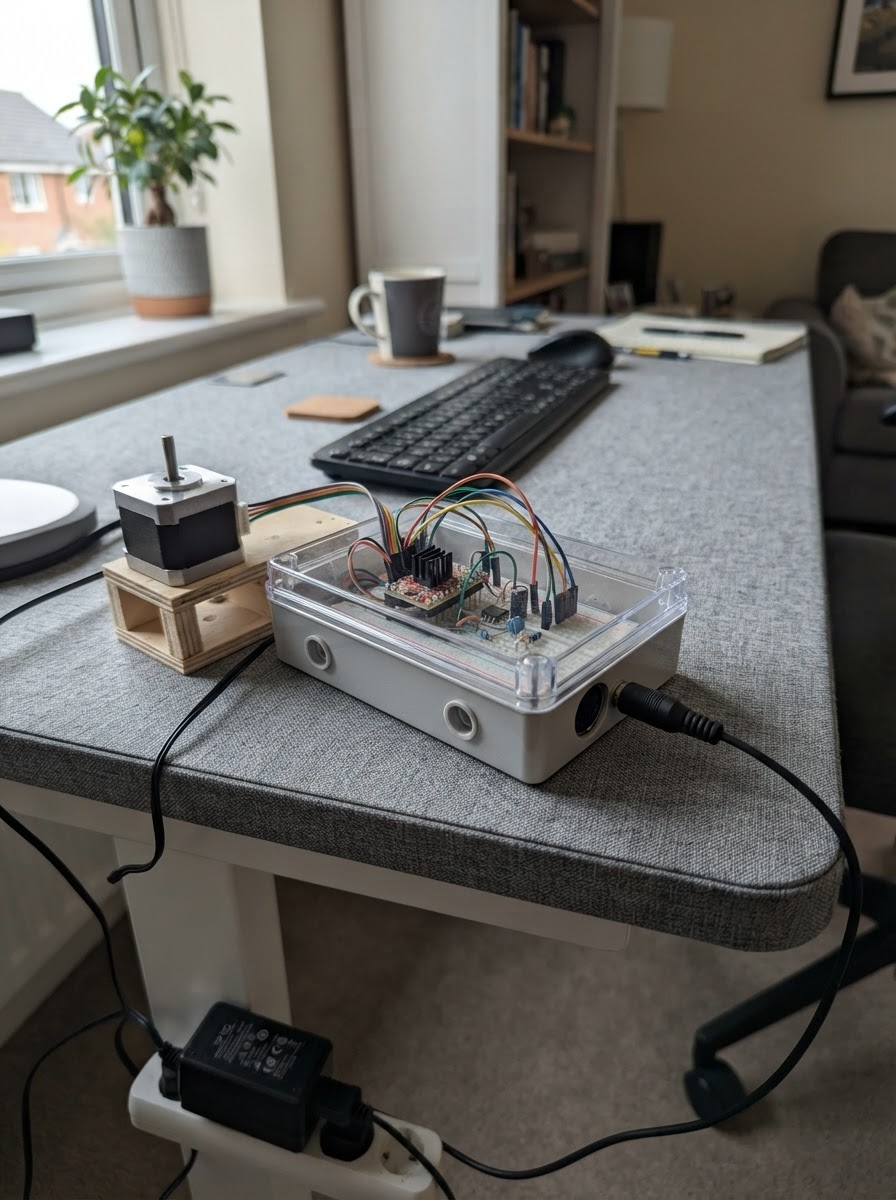
This guide builds a MIDI-controlled stepper motor controller that drives three NEMA 17 motors independently using MIDI note messages. Each motor's speed is controlled by MIDI note values (30 to 800 steps per second), making it suitable for kinetic sculptures, musical installations, or automated mechanical systems.
The project uses an Arduino Uno with three DRV8825 stepper drivers, an optoisolated MIDI input for noise immunity, and a 12 V power supply. This guide includes a complete wiring diagram, parts list, Arduino firmware with MIDI parsing and AccelStepper library integration, and step-by-step assembly instructions with safe power-up procedures.
Wiring diagram

Gather all the parts
Assemble it in 6 steps
1. Keep motor power unplugged while wiring
Place the Arduino Uno, the three DRV8825 boards, and the three motors on a non-metal surface. Leave the 12 V wall supply unplugged until every wire has been checked. Power the Arduino only from its USB cable.
- Put a small label on each driver and its matching motor: 1, 2, and 3.
- Do not plug or unplug a motor while its driver has power — that can permanently damage the DRV8825 board.
2. Wire the first motor driver
On driver 1, connect VDD to Arduino 5V (logic power), GND to Arduino GND (ground), STEP to D3 (step signal), and DIR to D4 (direction signal). Connect EN, M0, M1, and M2 to Arduino GND (ground); this keeps the driver enabled and uses full steps. Connect motor 1's two wires from one coil to 1A and 1B, and the other matching pair to 2A and 2B (motor power).
- Find each coil pair with a multimeter: the two wires that show a small resistance belong together. If the motor turns the wrong way, swap either one coil pair, not both.
- Set the tiny current-limit adjustment on the driver for your motor's rated current before regular use; start low to avoid overheating.
- Do not guess the motor coil pairs — crossed coils make the motor shudder instead of turning and can overheat it.
3. Wire the second and third motor drivers
For driver 2, connect VDD to Arduino 5V (logic power), GND to Arduino GND (ground), STEP to D5 (step signal), DIR to D6 (direction signal), and EN to GND (enable). Connect motor 2's two coil pairs to 1A/1B and 2A/2B (motor power). For driver 3, connect VDD to Arduino 5V (logic power), GND to Arduino GND (ground), STEP to D9 (step signal), DIR to D10 (direction signal), and EN to GND (enable). Connect motor 3's coil pairs to 1A/1B and 2A/2B (motor power).
- Keep the three driver boards separated so their adjustment screws and metal pins cannot touch.
- M0, M1, and M2 on drivers 2 and 3 may be left unconnected because their boards default to full steps; grounding them too is also acceptable if you wish to match driver 1.
- The 5 V Arduino pin powers only the small logic side of each driver; never connect a motor or a driver VMOT pin to Arduino 5 V.
4. Add the 12 V motor supply and capacitor
Connect the 12 V supply positive wire to VMOT on all three drivers (motor power). Connect the 12 V supply negative wire to GND on all three drivers and to an Arduino GND pin (shared ground). Place the 100 µF capacitor close to the driver boards: its long positive lead goes to the 12 V positive connection (spike protection), and its striped negative lead goes to the 12 V negative connection (ground).
- Use a proper screw-terminal splitter or terminal block for the 12 V positive and negative branches instead of forcing several wires into one small driver terminal.
- The capacitor's stripe marks its negative lead.
- Make sure the capacitor's positive and negative leads are not swapped — reversed electrolytic capacitors can fail violently.
- Check the 12 V supply polarity with a meter before plugging it into the drivers.
5. Build the isolated MIDI input
On the 5-pin MIDI socket, connect DIN-5 to one end of the 220 Ω resistor (MIDI signal), and connect the other resistor end to the 6N138 ANODE pin (MIDI signal). Connect DIN-4 to the 6N138 CATHODE pin (MIDI return). Leave DIN-2 unconnected. On the logic side of the 6N138, connect VCC to Arduino 5V (power), GND to Arduino GND (ground), and OUT to Arduino D2 (MIDI data). Connect the 10 kΩ resistor between Arduino 5V and the 6N138 OUT pin (signal pull-up).
- Verify the DIN socket contact numbers from the molded markings or its datasheet while looking at the solder side; connector views are easy to mirror.
- Keep the MIDI socket's DIN-2 shield contact disconnected so the MIDI device remains electrically isolated from the Arduino.
- Do not connect the MIDI socket contacts directly to an Arduino pin — the optocoupler is the small isolation part that protects the Arduino from the external MIDI device.
6. Make the first safe power-up
With the 12 V supply still unplugged, check every driver for a bridge between VMOT and VDD; these are different power connections and must not touch. Plug the Arduino into USB, then use Schematik's Deploy button to load the firmware. Finally, connect your MIDI device's MIDI OUT to the new MIDI socket with a standard MIDI cable, then plug in the 12 V supply.
- Start with one motor connected and a low driver current limit, then add the other two after it responds correctly.
- Send notes on MIDI channels 1, 2, and 3. Hold a note to run its corresponding motor; release it to stop.
- Keep fingers, loose clothing, and cables away from motor shafts and anything attached to them before applying 12 V power.
Review all connections
1. Connections between "motor_supply" and "Arduino"
2. Connections between "driver_1" and "Arduino"
3. Connections between "driver_2" and "Arduino"
4. Connections between "driver_3" and "Arduino"
5. Connections between "midi_input" and "Arduino"
6. Connections between "midi_r1" and "Arduino"
7. Connections between "midi_opto" and "Arduino"
8. Connections between "midi_pullup" and "Arduino"
Deploy the firmware
#include <AccelStepper.h>
#include <SoftwareSerial.h>


// Forward declarations
float noteToSpeed(uint8_t note);
void stopMotor(uint8_t index);
void handleMidiMessage(uint8_t status, uint8_t data1, uint8_t data2);
void readMidi();

const uint8_t MIDI_RX_PIN = 2;
const uint8_t MOTOR1_STEP_PIN = 3;
const uint8_t MOTOR1_DIR_PIN = 4;
const uint8_t MOTOR2_STEP_PIN = 5;
const uint8_t MOTOR2_DIR_PIN = 6;
const uint8_t MOTOR3_STEP_PIN = 9;
const uint8_t MOTOR3_DIR_PIN = 10;

const float MIN_SPEED = 30.0f;
const float MAX_SPEED = 800.0f;

SoftwareSerial midiSerial(MIDI_RX_PIN, 8); // RX only; pin 8 is unused TX.
AccelStepper motor1(AccelStepper::DRIVER, MOTOR1_STEP_PIN, MOTOR1_DIR_PIN);
AccelStepper motor2(AccelStepper::DRIVER, MOTOR2_STEP_PIN, MOTOR2_DIR_PIN);
AccelStepper motor3(AccelStepper::DRIVER, MOTOR3_STEP_PIN, MOTOR3_DIR_PIN);
AccelStepper *motors[3] = {&motor1, &motor2, &motor3};
int activeNote[3] = {-1, -1, -1};

uint8_t runningStatus = 0;
uint8_t dataBytes[2];
uint8_t dataCount = 0;

float noteToSpeed(uint8_t note) {
  return MIN_SPEED + (MAX_SPEED - MIN_SPEED) * ((float)note / 127.0f);
}

void stopMotor(uint8_t index) {
  motors[index]->setSpeed(0.0f);
  activeNote[index] = -1;
}

void handleMidiMessage(uint8_t status, uint8_t data1, uint8_t data2) {
  uint8_t command = status & 0xF0;
  uint8_t channel = (status & 0x0F) + 1;

  if (channel < 1 || channel > 3) {
    return;
  }

  uint8_t index = channel - 1;
  if (command == 0x90 && data2 > 0) {
    activeNote[index] = data1;
    motors[index]->setSpeed(noteToSpeed(data1));
  } else if (command == 0x80 || (command == 0x90 && data2 == 0)) {
    if (activeNote[index] == data1) {
      stopMotor(index);
    }
  }
}

void readMidi() {
  while (midiSerial.available() > 0) {
    uint8_t value = (uint8_t)midiSerial.read();

    if (value >= 0xF8) {
      continue; // MIDI timing and transport bytes can occur anywhere.
    }
    if (value & 0x80) {
      if (value >= 0x80 && value <= 0xEF) {
        runningStatus = value;
        dataCount = 0;
      } else {
        runningStatus = 0;
        dataCount = 0;
      }
      continue;
    }
    if (runningStatus == 0) {
      continue;
    }

    uint8_t command = runningStatus & 0xF0;
    uint8_t needed = (command == 0xC0 || command == 0xD0) ? 1 : 2;
    dataBytes[dataCount++] = value;
    if (dataCount >= needed) {
      if (needed == 2) {
        handleMidiMessage(runningStatus, dataBytes[0], dataBytes[1]);
      }
      dataCount = 0;
    }
  }
}

void setup() {
  midiSerial.begin(31250);

  for (uint8_t i = 0; i < 3; i++) {
    motors[i]->setMaxSpeed(MAX_SPEED);
    motors[i]->setSpeed(0.0f);
    motors[i]->setMinPulseWidth(3);
  }
}

void loop() {
  readMidi();
  motor1.runSpeed();
  motor2.runSpeed();
  motor3.runSpeed();
}
Remix this project
Make it yours in one click
Open a full copy of this project in your own Schematik workspace — diagram, code, parts, and assembly steps included. Swap the sensor, add features, or redesign the whole thing with AI. The author's original stays untouched.