Community project
Multi-Sensor Thermal Fence Alert
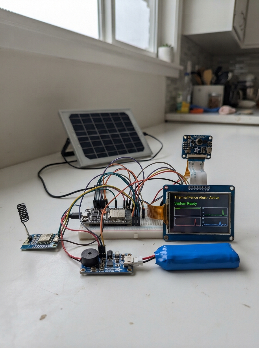
This project builds a distributed thermal monitoring system for perimeter security using LoRa wireless communication. Multiple fence-mounted sensor nodes equipped with infrared thermal cameras, motion detection, and tamper switches transmit alerts to a central receiver station displaying live thermal imagery and status on a touchscreen.
The guide provides a complete parts list, wiring diagrams for both the receiver unit and remote fence nodes, step-by-step assembly instructions, and firmware with LoRa packet handling, thermal image processing, and authentication. Builders will learn to integrate solar charging, battery management, long-range wireless protocols, and thermal imaging into a practical security application.
Wiring diagram

Gather all the parts
Assemble it in 5 steps
1. Build the indoor receiver
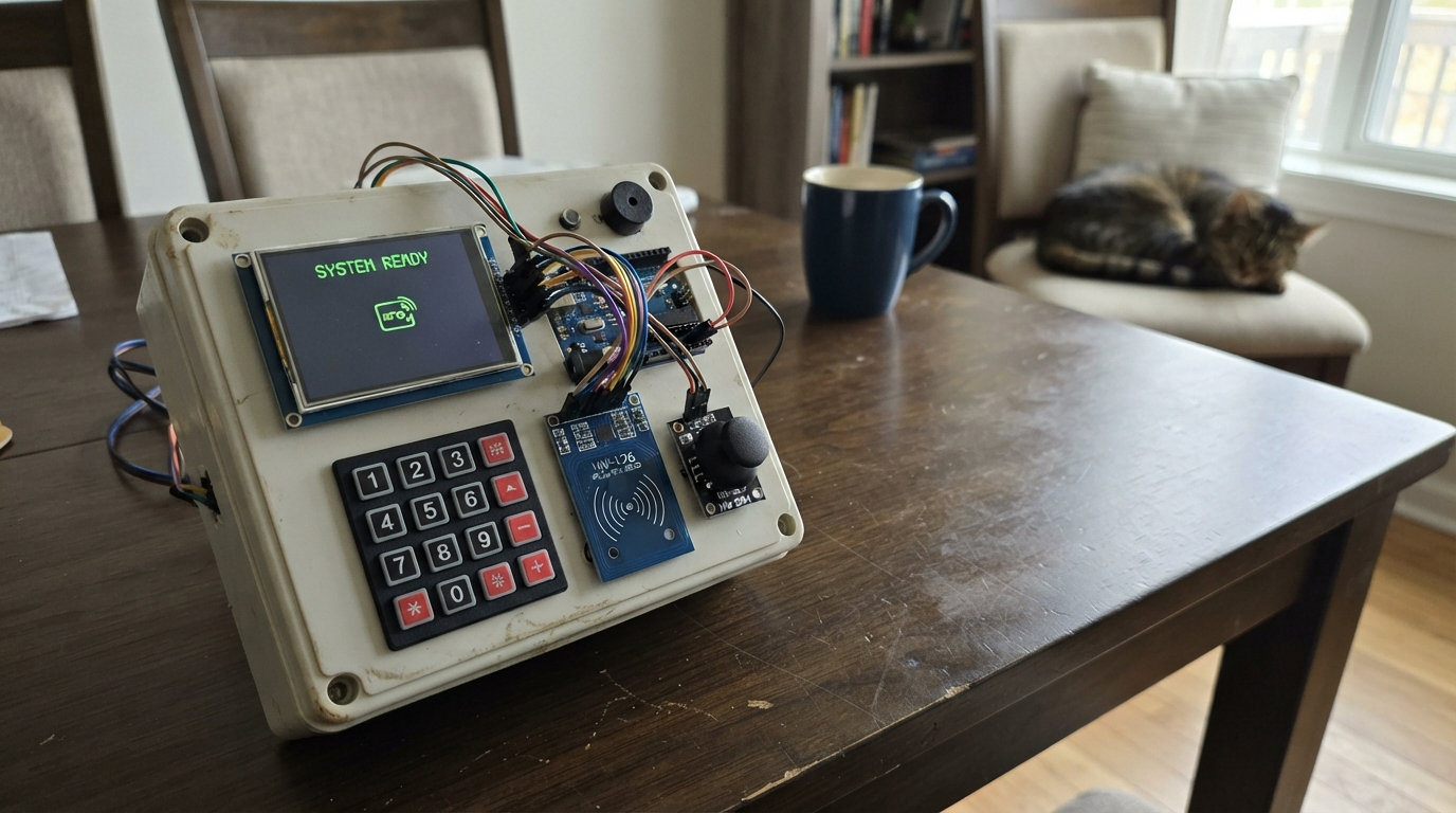
Keep the receiver ESP32 indoors and power it by USB. Connect the receiver LoRa radio: VCC → 3V3 (power), GND → GND (ground), MOSI → GPIO23 (data), MISO → GPIO19 (data), SCK → GPIO18 (clock), NSS → GPIO14 (radio select), RESET → GPIO33 (reset), and DIO0 → GPIO32 (received-message signal). Connect the screen using the same MOSI, MISO, and SCK wires, then TFT_CS → GPIO5 (screen select), TFT_DC → GPIO27 (screen control), TFT_RST → GPIO26 (screen reset), and TOUCH_CS → GPIO25 (touch controller select). Connect buzzer SIGNAL → GPIO4 (alert sound) and buzzer GND → GND (ground). Connect the new push button with one leg → GPIO13 (image request signal) and the other leg → GND (ground).
- The screen and radio share the three SPI data wires because each part has its own select wire.
- After a normal alert, press the new button once to ask that sensor for its saved heat frame.
- Make sure 3V3 and GND are not swapped — swapped power can damage the screen or radio.
- Do not use a 5 V supply on the LoRa radio; it is a 3.3 V part.
2. Make the protected battery connection
For each of the 12 identical fence units, connect battery BAT+ → fuse IN (battery protection). Connect fuse OUT → INA219 VIN+ (current measurement input), INA219 VIN- → charger BAT (protected battery feed), and battery BAT- → charger GND (ground). Connect charger 3V3 → controller 3V3 (power) and charger GND → controller GND (ground).
- The 10,000 mAh protected pack provides reserve for cloudy periods; actual winter performance still depends on shade, temperature, and solar exposure.
- Use crimp terminals, heat-shrink tubing, and strain relief so fence movement cannot pull battery wires loose.
- Never bypass the resettable fuse. A damaged cable without this protection can allow battery wiring to overheat.
- Use a ready-made protected 1S3P battery pack; do not build a multi-cell lithium pack from loose cells.
3. Wire the wake sensor, heat sensor, storage, and radio
Connect the motion sensor: VCC → charger 3V3 (power), GND → charger GND (ground), OUT → controller GPIO35 (wake signal). Connect the heat sensor: VCC → charger 3V3 (power), GND → charger GND (ground), SDA → controller GPIO21 (data), SCL → controller GPIO22 (clock). Connect the INA219 monitor: VCC → charger 3V3 (power), GND → charger GND (ground), SDA → controller GPIO21 (data), SCL → controller GPIO22 (clock). Connect the microSD module: VCC → charger 3V3 (power), GND → charger GND (ground), MOSI → controller GPIO23 (data), MISO → controller GPIO19 (data), SCK → controller GPIO18 (clock), CS → controller GPIO25 (card select). Connect the LoRa radio: VCC → charger 3V3 (power), GND → charger GND (ground), MOSI → controller GPIO23 (data), MISO → controller GPIO19 (data), SCK → controller GPIO18 (clock), NSS → controller GPIO13 (radio select), RESET → controller GPIO27 (reset), DIO0 → controller GPIO32 (radio-ready signal).
- The motion sensor is the first check; the thermal array then confirms a large warm object in the approximately 50-foot approach zone.
- The microSD card keeps the heat frame at the fence unit until you request it, so routine alerts stay short.
- The thermal array can flag a person-sized or vehicle-sized warm object in its 50-foot zone, but it cannot identify a person or make a normal camera photograph.
- Use only a microSD breakout that explicitly accepts 3.3 V logic and power.
4. Fit tamper protection and weatherproof the enclosure
Mount the magnetic tamper switch so its magnet is held next to the switch only when the lid is fully closed. Connect switch GND → controller GND (ground) and switch SIGNAL → controller GPIO34 (lid-open signal). Place the controller, charger, fuse, battery, and card inside a UV-resistant weatherproof enclosure. Connect solar V+ → charger VIN (charging power) and solar GND → charger GND (ground). Keep the thermal sensor behind a dry infrared-transparent opening and keep the LoRa antenna clear of metal.
- Use sealed cable glands and make a downward loop in every cable before it enters the box, so rain drips away.
- Aim the sensor across the fence approach zone and away from direct sunrise or sunset when possible.
- Do not cover the thermal sensor with ordinary glass or clear plastic; it blocks the heat wavelengths it needs.
- Do not put the antenna inside a metal enclosure; it can severely reduce reliable range.
5. Label and test one fence unit at a time
Give every fence unit a sensor number from 1 through 12 and record its exact fence location. Give every controller its own unique cryptographic key, message counter, and sensor number during programming. Test a warm-object alert, then press the receiver button to request the saved heat frame. Open the lid to test the tamper alert, then verify the receiver later shows each unit's battery and health check-in status.
- Finish the bench test before permanently sealing the box.
- Mount the first unit at the intended 50-foot zone and test it before duplicating the other eleven.
- Do not write private radio keys on the enclosure or share them in photos; a person who has a key could forge messages.
- A radio transmitter cannot be made undetectable. Keep it legal by transmitting only short authenticated alerts, requested heat frames, and infrequent health reports.
Review all connections
1. Connections between "lora_radio_1" and "ESP32"
2. Connections between "alert_display_1" and "ESP32"
3. Connections between "alert_buzzer_1" and "ESP32"
4. Connections between "fence_solar_panel_1" and "ESP32"
5. Connections between "fence_battery_1" and "ESP32"
6. Connections between "fence_charger_1" and "ESP32"
7. Connections between "fence_controller_1" and "ESP32"
8. Connections between "fence_thermal_1" and "ESP32"
9. Connections between "fence_lora_1" and "ESP32"
10. Connections between "fence_tamper_switch_1" and "ESP32"
11. Connections between "alert_image_button_1" and "ESP32"
12. Connections between "fence_battery_fuse_1" and "ESP32"
13. Connections between "fence_power_monitor_1" and "ESP32"
14. Connections between "fence_motion_wake_1" and "ESP32"
15. Connections between "fence_event_storage_1" and "ESP32"
Deploy the firmware
#include <Arduino.h>
#include <SPI.h>
#include <RadioLib.h>
#include <Adafruit_GFX.h>
#include <Adafruit_ILI9341.h>
#include <mbedtls/md.h>


// Forward declarations
void IRAM_ATTR onRadioReceive();
bool hasValidTag(const uint8_t *message, size_t length, const uint8_t *tag);
void addTag(uint8_t *message, size_t length);
void header(const char *text, uint16_t colour);
void beep(bool urgent);
uint16_t heatColour(uint8_t level);
void showReady();
void showAlert(uint8_t node, const char *kind);
void drawImage(uint8_t node);
void resetFrame(uint8_t node, uint8_t frame, uint8_t total);
void requestStoredImage();
void processPacket();

constexpr int LORA_NSS = 14;
constexpr int LORA_DIO0 = 32;
constexpr int LORA_RESET = 33;
constexpr int TFT_CS = 5;
constexpr int TFT_DC = 27;
constexpr int TFT_RST = 26;
constexpr int TOUCH_CS = 25;
constexpr int BUZZER_PIN = 4;
constexpr int REQUEST_BUTTON_PIN = 13;
constexpr int SPI_SCK = 18;
constexpr int SPI_MISO = 19;
constexpr int SPI_MOSI = 23;
constexpr uint8_t PACKET_MAGIC = 0xA7;
constexpr uint8_t IMAGE_PACKET = 0x01;
constexpr uint8_t TAMPER_PACKET = 0x02;
constexpr uint8_t ALERT_PACKET = 0x03;
constexpr uint8_t HEALTH_PACKET = 0x04;
constexpr uint8_t IMAGE_REQUEST_PACKET = 0x10;
constexpr uint8_t IMAGE_WIDTH = 32;
constexpr uint8_t IMAGE_HEIGHT = 24;
constexpr uint16_t IMAGE_PIXELS = IMAGE_WIDTH * IMAGE_HEIGHT;
constexpr uint8_t MAX_NODES = 12;
constexpr uint8_t MAX_CHUNKS = 12;
constexpr uint8_t HEADER_BYTES = 8;
constexpr uint8_t AUTH_BYTES = 8;
constexpr uint32_t FRAME_TIMEOUT_MS = 5000;
constexpr uint32_t BUTTON_DEBOUNCE_MS = 40;

// Replace this value before programming every receiver and fence controller.
// Each installation must use a private value not shared in labels or photographs.
const uint8_t AUTH_KEY[] = "FenceAlert-ChangeThisKey-2026!";
constexpr size_t AUTH_KEY_LENGTH = sizeof(AUTH_KEY) - 1;

Adafruit_ILI9341 tft(TFT_CS, TFT_DC, TFT_RST);
SX1276 radio = new Module(LORA_NSS, LORA_DIO0, LORA_RESET, -1);
uint8_t imageBuffer[IMAGE_PIXELS];
bool chunkSeen[MAX_CHUNKS] = {false};
uint8_t activeNode = 0, activeFrame = 0, expectedChunks = 0, chunksReceived = 0;
uint8_t latestAlertNode = 0;
uint8_t newestFrame[MAX_NODES + 1] = {0};
bool frameKnown[MAX_NODES + 1] = {false};
uint32_t lastChunkAt = 0, lastAlertAt = 0, lastButtonChange = 0;
bool lastButtonState = HIGH;
volatile bool radioPacketReady = false;

void IRAM_ATTR onRadioReceive() { radioPacketReady = true; }

bool hasValidTag(const uint8_t *message, size_t length, const uint8_t *tag) {
  uint8_t digest[32];
  mbedtls_md_context_t context;
  mbedtls_md_init(&context);
  const mbedtls_md_info_t *info = mbedtls_md_info_from_type(MBEDTLS_MD_SHA256);
  int status = mbedtls_md_setup(&context, info, 1);
  if (status == 0) status = mbedtls_md_hmac_starts(&context, AUTH_KEY, AUTH_KEY_LENGTH);
  if (status == 0) status = mbedtls_md_hmac_update(&context, message, length);
  if (status == 0) status = mbedtls_md_hmac_finish(&context, digest);
  mbedtls_md_free(&context);
  if (status != 0) return false;
  uint8_t difference = 0;
  for (uint8_t i = 0; i < AUTH_BYTES; ++i) difference |= digest[i] ^ tag[i];
  return difference == 0;
}

void addTag(uint8_t *message, size_t length) {
  uint8_t digest[32];
  mbedtls_md_context_t context;
  mbedtls_md_init(&context);
  const mbedtls_md_info_t *info = mbedtls_md_info_from_type(MBEDTLS_MD_SHA256);
  mbedtls_md_setup(&context, info, 1);
  mbedtls_md_hmac_starts(&context, AUTH_KEY, AUTH_KEY_LENGTH);
  mbedtls_md_hmac_update(&context, message, length);
  mbedtls_md_hmac_finish(&context, digest);
  mbedtls_md_free(&context);
  memcpy(&message[length], digest, AUTH_BYTES);
}

void header(const char *text, uint16_t colour = ILI9341_NAVY) {
  tft.fillRect(0, 0, 320, 30, colour);
  tft.setTextColor(ILI9341_WHITE, colour);
  tft.setTextSize(2); tft.setCursor(6, 7); tft.print(text);
}

void beep(bool urgent = false) {
  ledcAttachPin(BUZZER_PIN, 0);
  for (uint8_t i = 0; i < (urgent ? 3 : 2); ++i) {
    ledcWriteTone(0, urgent ? 2500 : 1800); delay(90);
    ledcWriteTone(0, 0); delay(60);
  }
}

uint16_t heatColour(uint8_t level) {
  uint8_t r = 0, g = 0, b = 0;
  if (level < 64) b = 80 + level * 2;
  else if (level < 128) { g = (level - 64) * 4; b = 255 - (level - 64) * 4; }
  else if (level < 192) { r = (level - 128) * 4; g = 255; }
  else { r = 255; g = 255 - (level - 192) * 4; }
  return tft.color565(r, g, b);
}

void showReady() {
  tft.fillScreen(ILI9341_BLACK); header("THERMAL FENCE RECEIVER");
  tft.setTextColor(ILI9341_WHITE); tft.setTextSize(2); tft.setCursor(18, 72);
  tft.print("Listening for 12 sensors");
  tft.setTextSize(1); tft.setCursor(18, 108);
  tft.print("50 ft large warm-object zone");
  tft.setCursor(18, 128); tft.print("Short authenticated alerts only");
  tft.setCursor(18, 148); tft.print("Press button after an alert for heat image");
}

void showAlert(uint8_t node, const char *kind) {
  tft.fillScreen(ILI9341_BLACK); header(kind, ILI9341_RED);
  tft.setTextColor(ILI9341_YELLOW); tft.setTextSize(3); tft.setCursor(28, 75);
  tft.print("SENSOR "); tft.print(node);
  tft.setTextColor(ILI9341_WHITE); tft.setTextSize(2); tft.setCursor(28, 132);
  tft.print("Large warm object"); tft.setCursor(28, 158); tft.print("in its 50 ft zone");
  tft.setTextSize(1); tft.setCursor(28, 210);
  tft.print("Press the image button to request its stored heat frame.");
}

void drawImage(uint8_t node) {
  header("STORED THERMAL FRAME"); tft.fillRect(0, 30, 320, 216, ILI9341_BLACK);
  for (uint8_t y = 0; y < IMAGE_HEIGHT; ++y)
    for (uint8_t x = 0; x < IMAGE_WIDTH; ++x)
      tft.fillRect(32 + x * 8, 42 + y * 8, 8, 8, heatColour(imageBuffer[y * IMAGE_WIDTH + x]));
  tft.fillRect(0, 246, 320, 74, ILI9341_BLACK); tft.setTextSize(2); tft.setTextColor(ILI9341_WHITE);
  tft.setCursor(12, 254); tft.print("Sensor "); tft.print(node); tft.print(" stored frame");
  tft.setCursor(12, 282); tft.setTextColor(ILI9341_CYAN); tft.print("Blue=cool   Red=warm");
}

void resetFrame(uint8_t node, uint8_t frame, uint8_t total) {
  activeNode = node; activeFrame = frame; expectedChunks = total; chunksReceived = 0;
  memset(chunkSeen, 0, sizeof(chunkSeen)); memset(imageBuffer, 0, sizeof(imageBuffer));
}

void requestStoredImage() {
  if (latestAlertNode == 0) return;
  uint8_t packet[HEADER_BYTES + AUTH_BYTES] = {PACKET_MAGIC, IMAGE_REQUEST_PACKET, latestAlertNode, 0, 0, 0, 0, 0};
  addTag(packet, HEADER_BYTES);
  radio.standby();
  int state = radio.transmit(packet, sizeof(packet));
  radio.startReceive();
  if (state == RADIOLIB_ERR_NONE) {
    tft.fillRect(0, 210, 320, 28, ILI9341_BLACK); tft.setTextColor(ILI9341_CYAN); tft.setTextSize(1);
    tft.setCursor(28, 216); tft.print("Image requested from Sensor "); tft.print(latestAlertNode);
  }
}

void processPacket() {
  uint8_t packet[255]; int16_t length = radio.getPacketLength();
  if (length < HEADER_BYTES + AUTH_BYTES || length > 255) return;
  if (radio.readData(packet, length) != RADIOLIB_ERR_NONE) return;
  uint16_t signedLength = length - AUTH_BYTES;
  if (packet[0] != PACKET_MAGIC || !hasValidTag(packet, signedLength, &packet[signedLength])) return;
  uint8_t type = packet[1], node = packet[2], frame = packet[3];
  if (node < 1 || node > MAX_NODES) return;
  if (type == TAMPER_PACKET) { latestAlertNode = node; showAlert(node, "ENCLOSURE OPEN"); beep(true); return; }
  if (type == ALERT_PACKET) { latestAlertNode = node; showAlert(node, "THERMAL ALERT"); beep(); return; }
  if (type == HEALTH_PACKET) return;
  if (type != IMAGE_PACKET) return;
  uint8_t chunk = packet[4], total = packet[5];
  uint16_t offset = (uint16_t(packet[6]) << 8) | packet[7];
  uint16_t dataLength = signedLength - HEADER_BYTES;
  if (!total || total > MAX_CHUNKS || chunk >= total || offset >= IMAGE_PIXELS || offset + dataLength > IMAGE_PIXELS) return;
  if (node != activeNode || frame != activeFrame || total != expectedChunks || millis() - lastChunkAt > FRAME_TIMEOUT_MS) {
    if (frameKnown[node] && frame == newestFrame[node]) return;
    resetFrame(node, frame, total); newestFrame[node] = frame; frameKnown[node] = true;
  }
  if (!chunkSeen[chunk]) { memcpy(&imageBuffer[offset], &packet[HEADER_BYTES], dataLength); chunkSeen[chunk] = true; ++chunksReceived; }
  lastChunkAt = millis();
  if (chunksReceived == expectedChunks) drawImage(activeNode);
}

void setup() {
  pinMode(TOUCH_CS, OUTPUT); digitalWrite(TOUCH_CS, HIGH);
  pinMode(BUZZER_PIN, OUTPUT); pinMode(REQUEST_BUTTON_PIN, INPUT_PULLUP);
  SPI.begin(SPI_SCK, SPI_MISO, SPI_MOSI); tft.begin(); tft.setRotation(1); showReady();
  if (radio.begin(915.0, 125.0, 9, 7, 0x12, 17) != RADIOLIB_ERR_NONE) {
    tft.setTextColor(ILI9341_RED); tft.setTextSize(2); tft.setCursor(18, 175); tft.print("Radio wiring error"); while (true) delay(1000);
  }
  radio.setDio0Action(onRadioReceive); radio.startReceive();
}

void loop() {
  if (radioPacketReady) { radioPacketReady = false; processPacket(); radio.startReceive(); }
  bool now = digitalRead(REQUEST_BUTTON_PIN);
  if (now != lastButtonState && millis() - lastButtonChange > BUTTON_DEBOUNCE_MS) {
    lastButtonChange = millis(); lastButtonState = now;
    if (now == LOW) requestStoredImage();
  }
  if (activeNode && millis() - lastChunkAt > FRAME_TIMEOUT_MS) resetFrame(0, 0, 0);
  delay(5);
}
Remix this project
Make it yours in one click
Open a full copy of this project in your own Schematik workspace — diagram, code, parts, and assembly steps included. Swap the sensor, add features, or redesign the whole thing with AI. The author's original stays untouched.