Community project
Multisensor Home Safety Alert System
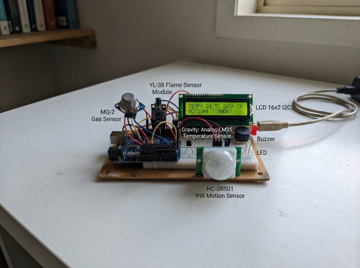
This multisensor home safety alert system combines gas, flame, temperature, and motion detection into a single Arduino-based monitoring station. Using an MQ-2 gas sensor, YL-38 flame detector, LM35 temperature sensor, and HC-SR501 motion sensor, the system continuously scans for hazardous conditions and displays real-time status on a 16x2 LCD screen with visual and audible warnings via LEDs and a buzzer.
This guide provides a complete parts list, wiring diagram showing all sensor connections to the Arduino Uno, step-by-step assembly instructions, and fully commented Arduino firmware ready to upload. Builders will learn how to integrate multiple analog and digital sensors, handle sensor calibration and warm-up periods, drive an I2C LCD display, and implement threshold-based alert logic—making it an ideal project for learning environmental monitoring and home automation fundamentals.
Wiring diagram

Gather all the parts
Assemble it in 10 steps
1. Place the Uno and prepare the rails
Put the Arduino Uno beside a full-size breadboard. Run one red jumper from Uno 5V to the breadboard red (+) rail and one black jumper from Uno GND to the blue/black (–) rail. If the rails are split in the middle, bridge each red half to the other red half and each ground half to the other ground half.
- Use these two rails as the only shared power and ground points for the small modules.
- Do not connect a 5 V rail to a GPIO pin; that can damage the Uno.
2. Connect the MQ-2 gas module
Place the MQ-2 module where its metal sensing can is clear of the breadboard. Connect MQ-2 VCC to the 5 V rail (power), GND to the ground rail (ground), and AO to Uno A0 (signal). Leave DO disconnected because this project measures the changing AO value instead.
- The module heater draws much more current than a GPIO can supply, so VCC must go to 5 V, never to a digital pin.
- The metal can becomes warm in normal use; do not touch it immediately after prolonged power-up.
3. Connect the flame sensor
Connect the YL-38 VCC pin to the 5 V rail (power), GND to the ground rail (ground), and DO to Uno D2 (signal). Leave AO disconnected. Aim the black infrared sensor at a flame only during a supervised demonstration.
- Turn the small sensitivity screw so DO is HIGH with no flame and changes LOW when a test flame is seen.
- Do not use a large flame or test near gas, paper, or other flammable items.
4. Connect the LM35 temperature module
Connect the LM35 module VCC/red wire to the 5 V rail (power), GND/black wire to the ground rail (ground), and SIG/blue wire to Uno A1 (temperature signal).
- If using a bare three-legged LM35 rather than the listed module, face its flat side toward you: left leg to 5 V, middle leg to A1, right leg to GND.
- Do not swap the LM35 power and ground wires; swapped power can damage the sensor.
5. Connect the motion sensor
Connect HC-SR501 VCC to the 5 V rail (power), GND to the ground rail (ground), and OUT to Uno D3 (motion signal). Keep its white dome facing the area where movement will be demonstrated.
- Set the HC-SR501 delay knob low and sensitivity around the middle for an easier classroom demonstration.
- Do not judge motion readings for the first 30 seconds after power-up because the PIR is settling.
6. Connect the LCD screen
Connect the 16×2 I2C LCD VCC to the 5 V rail (power), GND to the ground rail (ground), SDA to Uno A4 (data), and SCL to Uno A5 (clock). The board may also label A4/A5 as SDA/SCL.
- Adjust the small contrast screw on the LCD backpack if the backlight is on but letters are not visible.
- Make sure VCC and GND are not swapped — swapped power can damage the screen.
7. Build the four LED warning branches
For each LED, put its two legs in different breadboard rows. Put a 220 Ω resistor between the Uno output pin and the LED long leg (anode); connect the short leg (cathode, flat side) to the ground rail. Use D5 → gas_resistor → gas_led anode (gas warning), D6 → fire_resistor → fire_led anode (flame warning), D7 → temp_resistor → temp_led anode (temperature warning), and D8 → motion_resistor → motion_led anode (motion warning).
- Use red for gas, orange for flame, yellow for temperature, and blue for motion so the four warnings are easy to explain.
- Every LED needs its own 220 Ω resistor; connecting an LED straight to a Uno pin can overload the LED or pin.
8. Connect the small piezo buzzer
Connect buzzer SIGNAL or the + marked leg to Uno D4 (alarm signal) and buzzer GND or the – marked leg to the ground rail (ground).
- This design is for a small piezo/active buzzer only, not a siren, relay, or motor.
- Do not connect a high-current alarm siren directly to D4; it can damage the Uno.
9. Do the physical safety check
Trace every module ground wire back to the same ground rail, then trace every VCC wire to the 5 V rail. Check that only MQ-2 AO goes to A0, only LM35 SIG goes to A1, YL-38 DO goes to D2, PIR OUT goes to D3, and the LCD is on A4/A5.
- Compare each wire to the pin table before powering the board.
- Do not power the Uno from USB and a second unrelated 5 V supply at the same time.
10. Power and test the system
Plug the Uno into USB. Use Schematik’s Deploy button to flash the included firmware, then open its serial output. Wait at least 60 seconds for the MQ-2 warm-up message to finish and 30 seconds for the PIR to settle before testing each sensor.
- The serial output shows GasRaw and TempC so you can set a sensible gas threshold after observing clean-air readings.
- Use only a carefully controlled flame test; never release combustible gas indoors to test this student prototype.
Review all connections
1. Connections between "mq2_1" and "Arduino"
2. Connections between "flame_yl38_1" and "Arduino"
3. Connections between "lm35_1" and "Arduino"
4. Connections between "pir_1" and "Arduino"
5. Connections between "lcd_1" and "Arduino"
6. Connections between "buzzer_1" and "Arduino"
7. Connections between "gas_resistor" and "Arduino"
8. Connections between "gas_led" and "Arduino"
9. Connections between "fire_resistor" and "Arduino"
10. Connections between "fire_led" and "Arduino"
11. Connections between "temp_resistor" and "Arduino"
12. Connections between "temp_led" and "Arduino"
13. Connections between "motion_resistor" and "Arduino"
14. Connections between "motion_led" and "Arduino"
Deploy the firmware
#include <Arduino.h>
#include <Wire.h>
#include <LiquidCrystal_I2C.h>

// ----- Pin assignments -----

// Forward declarations
void showStatus(const String &line1, const String &line2);

const byte FLAME_PIN = 2;       // YL-38 DO: LOW means flame detected
const byte PIR_PIN = 3;         // HC-SR501 OUT: HIGH means motion
const byte BUZZER_PIN = 4;      // Small active 5 V piezo buzzer
const byte GAS_LED_PIN = 5;
const byte FIRE_LED_PIN = 6;
const byte TEMP_LED_PIN = 7;
const byte MOTION_LED_PIN = 8;
const byte MQ2_PIN = A0;        // MQ-2 AO
const byte LM35_PIN = A1;       // LM35 SIG

// ----- Adjustable demonstration thresholds -----
const int GAS_THRESHOLD = 350;              // Raw ADC level (0-1023), tune after observing clean-air readings
const float TEMPERATURE_THRESHOLD = 35.0;   // Degrees C; a configurable classroom demonstration warning level
const unsigned long MQ2_WARMUP_MS = 60000UL;
const unsigned long PIR_STABILIZE_MS = 30000UL;
const unsigned long BUZZER_ON_MS = 180UL;
const unsigned long BUZZER_PERIOD_MS = 700UL;

// Most common 16x2 I2C backpack address. Change to 0x3F only if your module uses that address.
LiquidCrystal_I2C lcd(0x27, 16, 2);

unsigned long startTime;
unsigned long lastDisplayUpdate = 0;
String lastLine1 = "";
String lastLine2 = "";

void showStatus(const String &line1, const String &line2) {
  // The LCD is changed only when its visible words need to change.
  if (line1 != lastLine1 || line2 != lastLine2) {
    lcd.clear();
    lcd.setCursor(0, 0);
    lcd.print(line1);
    lcd.setCursor(0, 1);
    lcd.print(line2);
    lastLine1 = line1;
    lastLine2 = line2;
  }
}

void setup() {
  pinMode(FLAME_PIN, INPUT);
  pinMode(PIR_PIN, INPUT);
  pinMode(BUZZER_PIN, OUTPUT);
  pinMode(GAS_LED_PIN, OUTPUT);
  pinMode(FIRE_LED_PIN, OUTPUT);
  pinMode(TEMP_LED_PIN, OUTPUT);
  pinMode(MOTION_LED_PIN, OUTPUT);

  digitalWrite(BUZZER_PIN, LOW);
  digitalWrite(GAS_LED_PIN, LOW);
  digitalWrite(FIRE_LED_PIN, LOW);
  digitalWrite(TEMP_LED_PIN, LOW);
  digitalWrite(MOTION_LED_PIN, LOW);

  Serial.begin(9600);
  lcd.init();
  lcd.backlight();
  startTime = millis();
  showStatus("Safety system", "Starting up...");

  Serial.println(F("Multisensor Home Safety Alert System"));
  Serial.println(F("MQ-2 gas readings are relative values, not calibrated ppm."));
  Serial.println(F("Wait for MQ-2 warm-up and PIR stabilization before testing."));
}

void loop() {
  const unsigned long now = millis();
  const bool mq2Ready = (now - startTime >= MQ2_WARMUP_MS);
  const bool pirReady = (now - startTime >= PIR_STABILIZE_MS);

  // 1. Read every sensor first.
  const int gasRaw = analogRead(MQ2_PIN);
  const int lm35Raw = analogRead(LM35_PIN);
  const float temperatureC = (lm35Raw * 5.0 * 100.0) / 1023.0;
  const bool flameDetected = (digitalRead(FLAME_PIN) == LOW);
  const bool motionDetected = pirReady && (digitalRead(PIR_PIN) == HIGH);

  // 2. Decide each hazard independently. MQ-2 and PIR are ignored only during their normal startup settling time.
  const bool gasDanger = mq2Ready && (gasRaw >= GAS_THRESHOLD);
  const bool fireDanger = flameDetected;
  const bool temperatureDanger = (temperatureC >= TEMPERATURE_THRESHOLD);
  const bool motionDanger = motionDetected;
  const bool anyDanger = gasDanger || fireDanger || temperatureDanger || motionDanger;

  // 3. Each LED directly follows its own hazard condition.
  digitalWrite(GAS_LED_PIN, gasDanger ? HIGH : LOW);
  digitalWrite(FIRE_LED_PIN, fireDanger ? HIGH : LOW);
  digitalWrite(TEMP_LED_PIN, temperatureDanger ? HIGH : LOW);
  digitalWrite(MOTION_LED_PIN, motionDanger ? HIGH : LOW);

  // 4. A repeating short beep avoids a continuous tone and never blocks sensor monitoring.
  const bool buzzerOn = anyDanger && ((now % BUZZER_PERIOD_MS) < BUZZER_ON_MS);
  digitalWrite(BUZZER_PIN, buzzerOn ? HIGH : LOW);

  // 5. Show the highest-priority active condition, or startup progress, on the LCD.
  if (fireDanger) {
    showStatus("FIRE ALERT!", "Check safely");
  } else if (gasDanger) {
    showStatus("GAS ALERT!", "Ventilate area");
  } else if (temperatureDanger) {
    showStatus("TEMP ALERT!", "High temperature");
  } else if (motionDanger) {
    showStatus("MOTION ALERT!", "Movement seen");
  } else if (!mq2Ready) {
    unsigned long secondsLeft = (MQ2_WARMUP_MS - (now - startTime) + 999UL) / 1000UL;
    showStatus("MQ-2 warming", String(secondsLeft) + " sec remaining");
  } else if (!pirReady) {
    unsigned long secondsLeft = (PIR_STABILIZE_MS - (now - startTime) + 999UL) / 1000UL;
    showStatus("PIR settling", String(secondsLeft) + " sec remaining");
  } else {
    showStatus("System Safe", "Monitoring...");
  }

  // Print calibration/debug readings twice each second without stopping the system.
  if (now - lastDisplayUpdate >= 500UL) {
    lastDisplayUpdate = now;
    Serial.print(F("GasRaw="));
    Serial.print(gasRaw);
    Serial.print(F(" TempC="));
    Serial.print(temperatureC, 1);
    Serial.print(F(" FlameDO="));
    Serial.print(digitalRead(FLAME_PIN));
    Serial.print(F(" PIR="));
    Serial.print(digitalRead(PIR_PIN));
    Serial.print(F(" Hazards G/F/T/M="));
    Serial.print(gasDanger);
    Serial.print('/');
    Serial.print(fireDanger);
    Serial.print('/');
    Serial.print(temperatureDanger);
    Serial.print('/');
    Serial.println(motionDanger);
  }
}
Remix this project
Make it yours in one click
Open a full copy of this project in your own Schematik workspace — diagram, code, parts, and assembly steps included. Swap the sensor, add features, or redesign the whole thing with AI. The author's original stays untouched.
Related projects
Soldering Stand with Fume Extractor and Lighting
Arduino · September 22, 2026prahaladh.pradeep
Smart Gait Analysis Platform
Arduino · September 22, 2026jose amorim
Automatische Pflanzenbewässerungskontrolle
Arduino · September 22, 2026michael.hasenberg