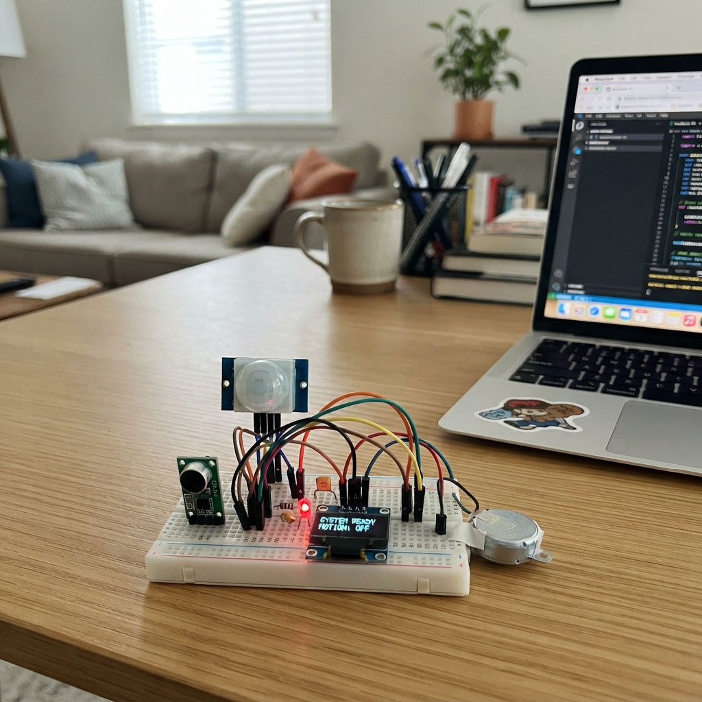
This multisensory home alert system combines sound and motion detection to trigger visual and tactile notifications. Built around an ESP32 microcontroller, it uses a KY-038 sound sensor and HC-SR501 PIR motion detector to monitor activity, with an SSD1306 OLED display showing real-time status, dual indicator LEDs for each sensor type, and a coin vibration motor for haptic feedback when both sensors detect activity within a short time window.
The guide provides a complete wiring diagram, parts list with power supply design, and step-by-step assembly instructions for the motor drive circuit with proper protection diodes and polarity checks. Firmware is included with configurable sensor thresholds and coincidence timing, plus calibration steps to tune the system for your specific room environment before mounting for household trials.
Wiring diagram
Gather all the parts
Assemble it in 7 steps
1. Prepare the board and low-voltage supply
Use a regulated 5 V USB supply rated at least 1 A through the board USB socket. Disconnect it while wiring. Use a breadboard and short jumpers, joining all grounds. VIN is the USB 5 V rail on this board; verify it measures about 5 V before connecting the PIR and regulator.
- Never connect household mains to the breadboard. Do not feed VIN from another supply while USB is connected.
2. Connect sound and motion inputs
Connect KY-038 VCC to 3V3, GND to GND and DO to GPIO32. Leave AO unconnected. Connect HC-SR501 VCC to VIN, GND to GND and OUT to GPIO33. Follow printed pin names, not assumed header order.
- Never power KY-038 from 5 V in this circuit. HC-SR501 OUT is 3.3 V despite its 5 V supply; verify before connection.
3. Add the display and two labeled lights
OLED VCC goes to 3V3, GND to GND, SDA to GPIO21 (data), SCL to GPIO22 (clock). GPIO25 goes through rs to the red SOUND LED anode; GPIO26 goes through rm to the green MOTION LED anode. Both LED short legs go to GND.
4. Build the protected vibration circuit
Use an AO3400A mounted on a labeled SOT-23 breadboard adapter. Pin 1 is gate, pin 2 source, pin 3 drain. GPIO27 goes through rg to gate, with pulldown from gate to GND. Source goes to GND and drain to motor minus. Regulator VIN goes to board VIN and GND to GND. Its 3.3 V output powers motor plus only; do not join it to board 3V3. Use the 3.3 V-rated motor variant with starting current no more than 150 mA.
- Use a complete regulator module with its input/output stability capacitors fitted, not a bare regulator IC.
5. Add motor protection and check polarity
Place diode across the motor, stripe to motor plus and unmarked end to motor minus. Place 100 nF bypass across motor terminals. Put bulk capacitor plus on the motor supply and minus on GND close to the driver. Measure the motor supply as 3.3 V before connecting the motor.
- Reversed diode can short the supply; reversed electrolytic capacitor may rupture.
6. Calibrate in the intended room
Allow 60 seconds of PIR warm-up. Set PIR jumper to L and hold-time trimmer to minimum; tune range sensitivity by walking through the intended area. Adjust KY-038 trimmer until quiet gives no alerts and your test sound consistently triggers. Some KY-038 clones invert DO; if needed change SOUND_ACTIVE in the code to LOW. Test sound, motion, and both within 100 ms.
- A PIR does not identify people or objects, or reliably detect someone sitting still. KY-038 does not identify sounds or measure calibrated decibels.
7. Mount for household trials
Use a compact nonconductive enclosure with openings for microphone and PIR lens and clear windows for OLED and labeled LEDs. Secure and insulate all connections. Mount motor on a surface the user touches and mechanically isolate microphone from it to reduce false sound triggers. Keep PIR away from heaters and direct sunlight. After breadboard tests transfer the same circuit to soldered prototyping board.
- Research prototype only: not a certified fire, security, medical or emergency alarm. Motor vibration can retrigger the microphone; test this before use.
Review all connections
1. Connections between "sound" and "ESP32"
2. Connections between "pir" and "ESP32"
3. Connections between "oled" and "ESP32"
4. Connections between "rs" and "ESP32"
5. Connections between "soundLed" and "ESP32"
6. Connections between "rm" and "ESP32"
7. Connections between "motionLed" and "ESP32"
8. Connections between "rg" and "ESP32"
9. Connections between "pulldown" and "ESP32"
10. Connections between "fet" and "ESP32"
11. Connections between "motor" and "ESP32"
12. Connections between "regulator" and "ESP32"
13. Connections between "diode" and "ESP32"
14. Connections between "bulk" and "ESP32"
15. Connections between "bypass" and "ESP32"
Deploy the firmware
#include <Arduino.h>
#include <Wire.h>
#include <Adafruit_GFX.h>
#include <Adafruit_SSD1306.h>
#include <esp_timer.h>
// Change to LOW if your KY-038 clone has inverted comparator output.
constexpr int SOUND_ACTIVE = HIGH;
constexpr int SOUND_PIN=32, PIR_PIN=33, SOUND_LED=25, MOTION_LED=26, MOTOR=27;
constexpr uint64_t COINCIDENCE_US=100000, SOUND_QUIET_US=300000;
Adafruit_SSD1306 screen(128,64,&Wire,-1);
bool screenOK=false, ready=false;
portMUX_TYPE mux=portMUX_INITIALIZER_UNLOCKED;
volatile uint64_t soundStamp=0, motionStamp=0, lastSoundEdge=0;
volatile bool soundPending=false, motionPending=false, soundArmed=true;
uint64_t nowUs(){return esp_timer_get_time();}
void IRAM_ATTR soundISR(){
  uint64_t t=esp_timer_get_time();
  portENTER_CRITICAL_ISR(&mux);
  lastSoundEdge=t;
  if(soundArmed){if(!soundPending){soundStamp=t;soundPending=true;}soundArmed=false;}
  portEXIT_CRITICAL_ISR(&mux);
}
void IRAM_ATTR motionISR(){
  portENTER_CRITICAL_ISR(&mux);
  if(!motionPending){motionStamp=esp_timer_get_time();motionPending=true;}
  portEXIT_CRITICAL_ISR(&mux);
}
struct Event{uint8_t mask; uint64_t s,m;};
Event queue[32], collecting={0,0,0}, active={0,0,0};
uint8_t head=0,tail=0,count=0; uint64_t collectStart=0,start=0;
bool running=false; int shown=-1;
void message(int state){
  if(shown==state)return; shown=state;
  if(!screenOK)return;
  screen.clearDisplay(); screen.setTextSize(1); screen.setTextColor(SSD1306_WHITE);
  screen.setCursor(0,12);
  const char* texts[]={"SYSTEM READY","SOUND DETECTED","MOTION DETECTED","BOTH DETECTED","PIR WARMUP: 60s"};
  screen.println(texts[state]); screen.display();
}
void logTime(const char* kind,uint8_t mask,uint64_t trigger,uint64_t output){
 Serial.printf("%s,%u,%llu,%llu,%llu\n",kind,mask,(unsigned long long)trigger,(unsigned long long)output,(unsigned long long)(output-trigger));
}
void enqueue(Event e){
 if(count==32){Serial.println("ERROR,QUEUE_OVERFLOW,event_lost");return;}
 queue[tail]=e;tail=(tail+1)%32;count++;
}
void setup(){
 Serial.begin(115200);
 pinMode(SOUND_LED,OUTPUT);pinMode(MOTION_LED,OUTPUT);pinMode(MOTOR,OUTPUT);
 digitalWrite(SOUND_LED,LOW);digitalWrite(MOTION_LED,LOW);digitalWrite(MOTOR,LOW);
 pinMode(SOUND_PIN,INPUT);pinMode(PIR_PIN,INPUT);
 Wire.begin(21,22);Wire.setTimeOut(50);
 screenOK=screen.begin(SSD1306_SWITCHCAPVCC,0x3C);
 if(!screenOK)Serial.println("ERROR,OLED_INIT_FAILED,LED_and_motor_continue");
 message(4);
 Serial.println("kind,mask,trigger_us,output_us,latency_us (mask: sound=1 motion=2 both=3)");
}
void loop(){
 uint64_t t=nowUs();
 if(!ready){
  if(t<60000000ULL){delay(1);return;}
  ready=true;
  attachInterrupt(digitalPinToInterrupt(SOUND_PIN),soundISR,SOUND_ACTIVE==HIGH?RISING:FALLING);
  attachInterrupt(digitalPinToInterrupt(PIR_PIN),motionISR,RISING);
  message(0);Serial.println("READY; motion requires a new LOW-to-HIGH transition");
 }
 bool s=false,m=false;uint64_t st=0,mt=0;
 portENTER_CRITICAL(&mux);
 if(soundPending){s=true;st=soundStamp;soundPending=false;}
 if(motionPending){m=true;mt=motionStamp;motionPending=false;}
 if(!soundArmed && t-lastSoundEdge>SOUND_QUIET_US && digitalRead(SOUND_PIN)!=SOUND_ACTIVE) soundArmed=true;
 portEXIT_CRITICAL(&mux);
 // Seal the previous window before adding events outside it.
 uint64_t earliest=s&&m?(st<mt?st:mt):(s?st:mt);
 if(collecting.mask && ((s||m) && earliest>collectStart+COINCIDENCE_US)){
  enqueue(collecting);collecting={0,0,0};
 }
 if(s||m){
  if(!collecting.mask)collectStart=earliest;
  if(s){collecting.mask|=1;collecting.s=st;logTime("TRIGGER_SOUND",1,st,st);}
  if(m){collecting.mask|=2;collecting.m=mt;logTime("TRIGGER_MOTION",2,mt,mt);}
 }
 if(collecting.mask && t>=collectStart+COINCIDENCE_US){enqueue(collecting);collecting={0,0,0};}
 if(!running && count){
  active=queue[head];head=(head+1)%32;count--;running=true;start=nowUs();
  digitalWrite(SOUND_LED,(active.mask&1)?HIGH:LOW);
  digitalWrite(MOTION_LED,(active.mask&2)?HIGH:LOW);digitalWrite(MOTOR,HIGH);
  uint64_t out=nowUs();
  if(active.mask&1)logTime("LED_MOTOR_SOUND",active.mask,active.s,out);
  if(active.mask&2)logTime("LED_MOTOR_MOTION",active.mask,active.m,out);
  message(active.mask);out=nowUs();
  if(active.mask&1)logTime("OLED_TRANSFER_SOUND",active.mask,active.s,out);
  if(active.mask&2)logTime("OLED_TRANSFER_MOTION",active.mask,active.m,out);
 }
 if(running){
  uint64_t elapsed=nowUs()-start;
  bool on;uint64_t duration;
  if(active.mask==2){on=elapsed<700000;duration=1200000;}
  else {int pulses=active.mask==3?3:2;on=elapsed<uint64_t(pulses)*400000 && elapsed%400000<180000;duration=uint64_t(pulses)*400000+500000;}
  digitalWrite(MOTOR,on);digitalWrite(SOUND_LED,on&&(active.mask&1));digitalWrite(MOTION_LED,on&&(active.mask&2));
  if(elapsed>=duration){running=false;digitalWrite(MOTOR,LOW);digitalWrite(SOUND_LED,LOW);digitalWrite(MOTION_LED,LOW);message(0);}
 }
 delay(1);
}
Remix this project
Make it yours in one click
Open a full copy of this project in your own Schematik workspace, diagram, code, parts, and assembly steps included. Swap the sensor, add features, or redesign the whole thing with AI. The author's original stays untouched.