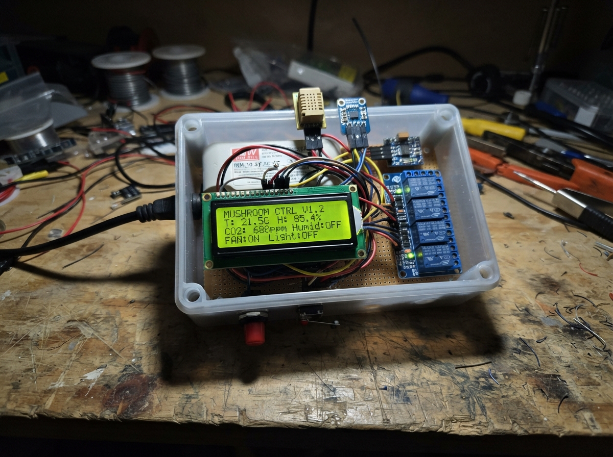
This guide builds a complete environmental controller for mushroom cultivation using an ESP32 microcontroller, CO2 and humidity sensors, and relay-controlled dampers. The system monitors temperature, humidity, and CO2 levels while automating intake and exhaust dampers, humidification, heating, and lighting based on user-defined setpoints. Operators interact via a 20x4 LCD display and four push buttons to set targets and view real-time conditions.
The guide provides a complete wiring diagram showing safe separation of mains and low-voltage circuits, a full parts list with part numbers, Arduino firmware with damper sequencing and sensor polling, and step-by-step assembly instructions. Safety features include proof-of-position microswitches on the dampers, a solid-state relay for heating, and a watchdog timer to prevent unsafe states. The design is ready for an electrician to connect the final AC loads once low-voltage testing is complete.
Wiring diagram
Gather all the parts
Assemble it in 7 steps
1. Keep mains work separate
Build and test the low-voltage controller first. A qualified electrician must install the IRM-10-5 on a mains-rated PCB inside a dry enclosure, with fused input, strain relief, earthing where required and RCD protection. Never put 220V on a breadboard. Disconnect the external 5V supply before plugging USB into the board to avoid competing supplies.
- 220V can kill. Relay contacts and SSR outputs remain hazardous even when commanded off. SSRs can fail shorted; a separate heater high-limit cutout and disconnect are mandatory.
2. Wire the shared sensor bus
SCD41 and SHT35 VCC go to 3V3; GND to GND; SDA to GPIO8 (data); SCL to GPIO9 (clock). Use SHT35 breakout address 0x44 with pullups to 3.3V. Keep the sensors out of direct humidifier spray and condensation.
3. Connect the screen safely
Use a common PCF8574 20x4 backpack at 0x27, not the DFR0154 0x20 model. LCD VCC goes to the main 5V rail and GND to GND. Level booster VIN goes to 3V3, G to GND, 3DA to GPIO8 and 3CL to GPIO9. Connect 5DA/5CL to LCD SDA/SCL. Leave the booster's 5V output unconnected; the LCD uses the main 5V supply. Adjust the contrast screw.
4. Connect buttons and open-position proof
UP/DOWN/EDIT/BACK switches go between GPIO4/5/6/7 respectively and GND. Mount one dry-contact microswitch on each damper so its NO contact closes only at fully open: COM to GND, NO to GPIO17 for damper 1 and GPIO18 for damper 2. Insulate unused NC terminals. Do not connect mains actuator auxiliary contacts unless proven isolated dry contacts.
- The timer alone cannot prove a damper opened. These two position switches are required for fan enable. A shorted proof cable can falsely indicate open; this controller is not a certified safety system.
5. Wire direct relay logic and the SSR driver
Remove the VCC/JD-VCC jumper before powering anything. Relay VCC goes to ESP32 3V3; JD-VCC (also labelled RY-VCC) goes to Mean Well 5V; GND goes to common GND. Connect IN1-IN6 directly to GPIO11-GPIO16, respectively. IN7/IN8 go to 3V3 to stay off. Only the SSR uses a transistor. GPIO10 goes through base7 (1 kohm) to q7 base; off7 (10 kohm) goes from base to GND; emitter goes to GND; collector goes to SSR minus; SSR plus goes to 5V. Verify the transistor's exact E/B/C pin order.
- Common ground means this split-power configuration is not galvanically isolated. Never reconnect the jumper with VCC wired to 3V3.
- Test that every relay is off during startup and reset before connecting mains loads. Software cannot guarantee relay state while GPIOs float during reset.
6. Have the electrician connect the loads
Channel 1 exhaust, 2 intake, 3 humidifier, 4 both dampers OPEN, 5 both dampers CLOSE, 6 light; channels 7/8 unused. This design requires mains-rated three-wire bidirectional actuators with internal end-stop switches, with BOTH dampers sharing the direction commands. Use mechanically/electrically interlocked directional contactors for open/close so welded relay contacts cannot energize both directions. For each ordinary load, protected live goes to COM and NO to load live; neutral directly to load neutral. Protective earth must never be switched. SSR terminal 1 gets protected live through an independent overtemperature cutout; terminal 2 goes to heater live. Fit a correctly sized heat sink. Size fuses, contactors and motor suppression for actual load current/inrush, not the relay's nominal resistive rating.
- Different damper actuator types need different mains wiring. Never apply this wiring to two-wire spring-return or DC actuators. External mains loads, contactors, cutout and protection are electrician-installed equipment outside the low-voltage diagram.
7. Test before enabling mains loads
Test with all load power isolated. At startup the fans remain off while a closing cycle runs. Raise CO2 demand: opening commands run for 10 seconds and both proof contacts must be closed for fans to start. Disconnect either proof contact: fans must stop and a fault must latch. Ending ventilation stops fans, waits 2 seconds, then closes dampers. CLOSED on the screen is timer-inferred, not measured. Set travel time in firmware to at least the actuator's actual full-stroke time; 10 seconds is only a starting example. EDIT opens the menu; UP/DOWN select or adjust; EDIT saves; BACK cancels. Fault reset does not require open proof contacts; it clears the fault and restarts the safe stop-and-close sequence. Serial debugging runs at 115200 baud every 3 seconds. A 30-second watchdog resets the controller if its loop hangs; it is not a heater safety cutout. Light is manually toggled in its menu and starts off.
Review all connections
1. Connections between "psu" and "ESP32"
2. Connections between "co2" and "ESP32"
3. Connections between "sht" and "ESP32"
4. Connections between "shift" and "ESP32"
5. Connections between "lcd" and "ESP32"
6. Connections between "up" and "ESP32"
7. Connections between "down" and "ESP32"
8. Connections between "edit" and "ESP32"
9. Connections between "back" and "ESP32"
10. Connections between "open1" and "ESP32"
11. Connections between "open2" and "ESP32"
12. Connections between "relays" and "ESP32"
13. Connections between "base7" and "ESP32"
14. Connections between "off7" and "ESP32"
15. Connections between "q7" and "ESP32"
16. Connections between "ssr" and "ESP32"
Deploy the firmware
#include <Arduino.h>
#include <esp_task_wdt.h>
#include <esp_idf_version.h>
#include <Wire.h>
#include <SPI.h>
#include <Preferences.h>
#include <SensirionI2cScd4x.h>
#include <Adafruit_SHT31.h>
#include <LiquidCrystal_I2C.h>
// Relay channels are active LOW; SSR transistor is active HIGH.
const int OUT[]={11,12,13,14,15,16,10}; // exhaust,intake,humidity,open,close,light,heat
const int BTN[]={4,5,6,7};
const uint32_t TRAVEL=10000, STOP=2000, DEAD=500;
SensirionI2cScd4x scd; Adafruit_SHT31 sht; LiquidCrystal_I2C lcd(0x27,20,4); Preferences pref;
float spT=26,spH=85,spC=1000,t=NAN,h=NAN; uint16_t co2=0;
uint32_t thAt=0,cAt=0,pollAt=0,phaseAt=0,proofAt=0;
bool gotTH=false,gotC=false,heat=false,humid=false,vent=false,light=false,fault=false,editing=false;
int page=0; float draft=0;
enum Phase {UNKNOWN,STOPPING,CLOSING,CLOSED,WAIT_OPEN,OPENING,OPEN}; Phase phase=UNKNOWN;
bool outputs[7]={};
void out(int i,bool v){ if(outputs[i]!=v){outputs[i]=v;digitalWrite(OUT[i],i==6?(v?HIGH:LOW):(v?LOW:HIGH));} }
void fans(bool v){out(0,v);out(1,v);}
void enter(Phase p){phase=p;phaseAt=millis();}
bool proof(){return digitalRead(17)==LOW&&digitalRead(18)==LOW;}
void latchFault(){fault=true;fans(false);out(3,false);out(4,false);out(2,false);out(6,false);heat=humid=vent=false;}
void dampers(uint32_t now,bool demand){
 if(fault){fans(false);return;}
 switch(phase){
 case UNKNOWN: fans(false);out(3,false);out(4,false);enter(STOPPING);break;
 case STOPPING: fans(false);out(3,false);if(now-phaseAt>=STOP){out(4,true);enter(CLOSING);}break;
 case CLOSING: if(now-phaseAt>=TRAVEL){out(4,false);enter(CLOSED);}break;
 case CLOSED: if(demand){out(4,false);enter(WAIT_OPEN);}break;
 case WAIT_OPEN: if(now-phaseAt>=DEAD){out(3,true);proofAt=now;enter(OPENING);}break;
 case OPENING:
  if(!proof())proofAt=now;
  if(now-phaseAt>=TRAVEL){if(proof()&&now-proofAt>=200){out(3,false);enter(OPEN);}else if(now-phaseAt>=TRAVEL+3000)latchFault();}break;
 case OPEN:
  if(!proof()){latchFault();break;}
  if(!demand){fans(false);enter(STOPPING);}else fans(true);break;
 }
}
int buttonEvent(){static bool raw[4]={1,1,1,1},stable[4]={1,1,1,1};static uint32_t at[4]={};
 int ev=-1;for(int i=0;i<4;i++){bool r=digitalRead(BTN[i]);if(r!=raw[i]){raw[i]=r;at[i]=millis();}if(millis()-at[i]>=35&&stable[i]!=r){stable[i]=r;if(!r)ev=i;}}return ev;}
float current(){return page==1?spT:page==2?spH:spC;}
void ui(){int b=buttonEvent();if(b<0)return;
 if(b==3){editing=false;page=0;return;}
 if(b==2){if(page==0){page=1;return;}if(page==4){light=!light;return;}if(page==5){fault=false;enter(UNKNOWN);return;}if(!editing){draft=current();editing=true;}else{if(page==1)spT=draft;if(page==2)spH=draft;if(page==3)spC=draft;pref.putFloat("t",spT);pref.putFloat("h",spH);pref.putFloat("c",spC);editing=false;}return;}
 int d=b==0?1:-1;if(editing){draft+=d*(page==1?0.5f:page==2?1.f:50.f);draft=constrain(draft,page==1?5.f:page==2?30.f:400.f,page==1?35.f:page==2?95.f:5000.f);}else{page+=d;if(page<0)page=5;if(page>5)page=0;}}
void display(){static char old[4][21]={{}};char rows[4][21]={{}};
 if(page==0){if(gotTH)snprintf(rows[0],21,"T=%.1fC H=%.0f%%",t,h);else strcpy(rows[0],"T=--- H=---");if(gotC)snprintf(rows[1],21,"A=%uppm",co2);else strcpy(rows[1],"A=---ppm");snprintf(rows[2],21,"D:%s",fault?"FAULT":phase==OPEN?"OPEN":phase==CLOSED?"CLOSED*":"MOVING");snprintf(rows[3],21,"%s L:%s",(!gotTH||!gotC||millis()-thAt>15000||millis()-cAt>20000)?"SENSOR FAULT":"EDIT: menu",light?"ON":"OFF");}
 else{const char* names[]={"","Temperature C","Humidity %","CO2 ppm","Light manual","Damper fault reset"};strncpy(rows[0],names[page],20);if(page<=3)snprintf(rows[1],21,"%s %.1f",editing?"Edit":"Set",editing?draft:current());else snprintf(rows[1],21,"%s",page==4?(light?"ON":"OFF"):(fault?"FAULT":"OK"));strcpy(rows[2],"UP/DOWN: change");strcpy(rows[3],editing?"EDIT save BACK cancel":"EDIT select BACK home");}
 for(int r=0;r<4;r++){size_t n=strlen(rows[r]);while(n<20)rows[r][n++]=' ';rows[r][20]=0;if(strcmp(old[r],rows[r])){lcd.setCursor(0,r);lcd.print(rows[r]);strcpy(old[r],rows[r]);}}}
void setup(){Serial.begin(115200);
 for(int i=0;i<7;i++){digitalWrite(OUT[i],i==6?LOW:HIGH);pinMode(OUT[i],OUTPUT);}
 #if ESP_IDF_VERSION_MAJOR >= 5
 esp_task_wdt_config_t cfg={};cfg.timeout_ms=30000;cfg.idle_core_mask=0;cfg.trigger_panic=true;
 esp_err_t wd=esp_task_wdt_init(&cfg);if(wd==ESP_ERR_INVALID_STATE)wd=esp_task_wdt_reconfigure(&cfg);
 #else
 esp_err_t wd=esp_task_wdt_init(30,true);
 #endif
 if(wd!=ESP_OK || esp_task_wdt_add(NULL)!=ESP_OK){Serial.println("Watchdog setup failed; outputs remain OFF");while(true)delay(1000);}
for(int p:BTN)pinMode(p,INPUT_PULLUP);pinMode(17,INPUT_PULLUP);pinMode(18,INPUT_PULLUP);
 Wire.begin(8,9);Wire.setClock(100000);Wire.setTimeOut(50);lcd.init();lcd.backlight();pref.begin("climate",false);spT=constrain(pref.getFloat("t",26),5.f,35.f);spH=constrain(pref.getFloat("h",85),30.f,95.f);spC=constrain(pref.getFloat("c",1000),400.f,5000.f);
 sht.begin(0x44);scd.begin(Wire, 0x62);scd.stopPeriodicMeasurement();delay(500);scd.setAutomaticSelfCalibrationEnabled(false);scd.startPeriodicMeasurement();}
void loop(){esp_task_wdt_reset();uint32_t now=millis();ui();
 if(now-pollAt>=2000){pollAt=now;float nt=sht.readTemperature(),nh=sht.readHumidity();if(isfinite(nt)&&isfinite(nh)&&nh>=0&&nh<=100){t=nt;h=nh;thAt=now;gotTH=true;}
 bool ready=false;if(!scd.getDataReadyStatus(ready)&&ready){uint16_t nc;float ct,ch;if(!scd.readMeasurement(nc,ct,ch)&&nc>0){co2=nc;cAt=now;gotC=true;}}}
 bool okTH=gotTH&&now-thAt<15000,okC=gotC&&now-cAt<20000;
 if(okTH&&!fault){if(t<=spT-0.5)heat=true;if(t>=spT+0.5)heat=false;if(h<=spH-3)humid=true;if(h>=spH+3)humid=false;if(t>=35)heat=false;}else heat=humid=false;
 if(okC&&okTH&&!fault){if(co2>=spC+100)vent=true;if(co2<=spC-100)vent=false;}else vent=false;
 out(6,heat);out(2,humid);out(5,light);dampers(now,vent);display();
 static uint32_t logAt=0;if(now-logAt>=3000){logAt=now;
 const char* phases[]={"UNKNOWN","STOPPING","CLOSING","CLOSED","WAIT_OPEN","OPENING","OPEN"};
 Serial.printf("T=%.2fC H=%.1f%% CO2=%u ppm THvalid=%d CO2valid=%d phase=%s fault=%d proof=%d heat=%d humid=%d vent=%d\n",t,h,co2,okTH,okC,phases[phase],fault,proof(),heat,humid,vent);}
 delay(10);
}
Remix this project
Make it yours in one click
Open a full copy of this project in your own Schematik workspace, diagram, code, parts, and assembly steps included. Swap the sensor, add features, or redesign the whole thing with AI. The author's original stays untouched.