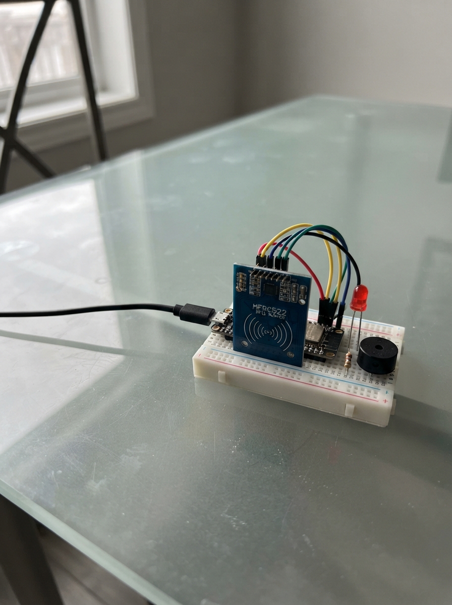
This project builds an offline RFID attendance tracker that logs when people enter and leave a space using RFID card taps. The ESP32 microcontroller reads RFID cards via the MFRC522 module, toggles an LED to show occupancy status, and provides audio feedback through a piezo buzzer. The system stores attendance records locally and serves them on a web interface accessible over WiFi, making it ideal for classrooms or small offices that need simple, reliable attendance tracking without cloud connectivity.
This guide provides a complete parts list, wiring diagram showing how to connect the RFID reader, LED, resistor, and buzzer to the ESP32, and step-by-step assembly instructions. The included firmware handles card detection, tracks entry and exit status for up to 100 unique cards, and displays real-time attendance data through a built-in web server. Builders will learn how to interface with RFID hardware, manage state tracking, and create a functional web interface on an embedded device.
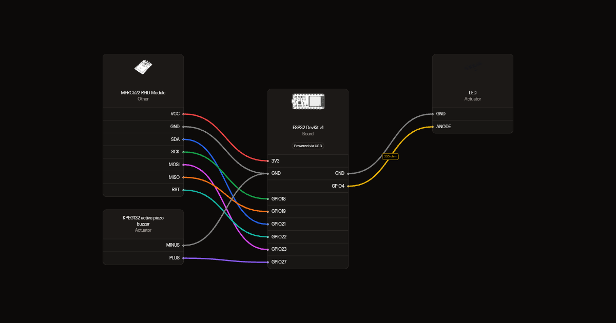
Wiring diagram
Gather all the parts
Assemble it in 5 steps
1. Place the board and prepare power rails
Disconnect USB. Place the ESP32 across the breadboard center gap with its USB socket accessible. If it leaves no usable holes, use two breadboards. Connect 3V3 to the positive rail and GND to the ground rail. Bridge split rails if necessary.
- Do not connect USB 5 V to the 3.3 V rail.
2. Connect the RFID reader
Connect VCC (marked 3.3V) to 3V3 and GND to ground. Connect SDA/SS to GPIO21, SCK to GPIO18, MOSI to GPIO23, MISO to GPIO19 and RST to GPIO22. Leave IRQ disconnected. Keep wires short.
- SDA is SPI chip select on this reader, not I2C data. GPIO21 replaces the requested boot-strapping GPIO5.
3. Add the occupied light
Connect GPIO4 to one end of the 220 ohm resistor. Connect its other end to the green LED long leg (anode). Connect the short leg (cathode, flat edge) to ground. Use separate breadboard rows for the two LED legs.
4. Add tap feedback
Connect KPEG132 buzzer positive to GPIO27 and negative to ground. GPIO27 replaces the requested boot-strapping GPIO15.
- Use this low-current active piezo buzzer for direct GPIO drive. A generic higher-current buzzer needs a transistor driver; do not substitute one directly.
5. Check before powering
Check polarity, shared ground, and each GPIO label, not header position. Power only through the ESP32 micro-USB port with a regulated 5 V USB supply.
- RC522 supply and signals must remain 3.3 V.
Review all connections
1. Connections between "reader" and "ESP32"
2. Connections between "led_resistor" and "ESP32"
3. Connections between "occupied" and "ESP32"
4. Connections between "feedback" and "ESP32"
Deploy the firmware
#include <Arduino.h>
#include <SPI.h>
#include <MFRC522.h>
#include <WiFi.h>
#include <WebServer.h>
constexpr int SS_PIN=21, RST_PIN=22, LED_PIN=4, BUZZER_PIN=27;
MFRC522 reader(SS_PIN,RST_PIN);
WebServer server(80);
struct Entry { String uid; bool inside=false; unsigned long changed=0; };
Entry entries[100];
int used=0;
unsigned long beepStart=0;
bool beeping=false;
String lastUid;
unsigned long lastTap=0;
void page(){
 String html="<!doctype html><html><head><meta name='viewport' content='width=device-width'><meta http-equiv='refresh' content='5'><title>Attendance</title></head><body><h1>Classroom attendance</h1><p>Times are seconds since startup. Records reset on restart.</p><table border='1'><tr><th>Card UID</th><th>Status</th><th>Last change (s)</th></tr>";
 int count=0;
 for(int i=0;i<used;i++){count+=entries[i].inside;html+="<tr><td>"+entries[i].uid+"</td><td>"+(entries[i].inside?String("Inside"):String("Outside"))+"</td><td>"+String(entries[i].changed/1000)+"</td></tr>";}
 html+="</table><p>People inside: "+String(count)+"</p><p>Remove your card before tapping again. Maximum 100 cards.</p></body></html>";
 server.send(200,"text/html",html);
}
void setup(){
 Serial.begin(115200);
 pinMode(LED_PIN,OUTPUT); digitalWrite(LED_PIN,LOW);
 pinMode(BUZZER_PIN,OUTPUT);digitalWrite(BUZZER_PIN,LOW);
 SPI.begin(18,19,23,SS_PIN);reader.PCD_Init();
 WiFi.mode(WIFI_AP);WiFi.softAP("Classroom-Attendance","Classroom123");
 server.on("/",page);server.begin();Serial.println(WiFi.softAPIP());
}
void loop(){
 server.handleClient();
 if(beeping && millis()-beepStart>=100){digitalWrite(BUZZER_PIN,LOW);beeping=false;}
 if(!reader.PICC_IsNewCardPresent() || !reader.PICC_ReadCardSerial())return;
 String uid;
 for(byte i=0;i<reader.uid.size;i++){if(reader.uid.uidByte[i]<16)uid+="0";uid+=String(reader.uid.uidByte[i],HEX);}uid.toUpperCase();
 reader.PICC_HaltA();reader.PCD_StopCrypto1();
 if(uid==lastUid && millis()-lastTap<1500)return;
 lastUid=uid;lastTap=millis();
 int index=0;while(index<used && entries[index].uid!=uid)index++;
 if(index==used){if(used>=100)return;entries[used++].uid=uid;}
 entries[index].inside=!entries[index].inside;entries[index].changed=millis();
 bool occupied=false;for(int i=0;i<used;i++)occupied|=entries[i].inside;
 digitalWrite(LED_PIN,occupied?HIGH:LOW);
 digitalWrite(BUZZER_PIN,HIGH);beeping=true;beepStart=millis();
}
Remix this project
Make it yours in one click
Open a full copy of this project in your own Schematik workspace, diagram, code, parts, and assembly steps included. Swap the sensor, add features, or redesign the whole thing with AI. The author's original stays untouched.