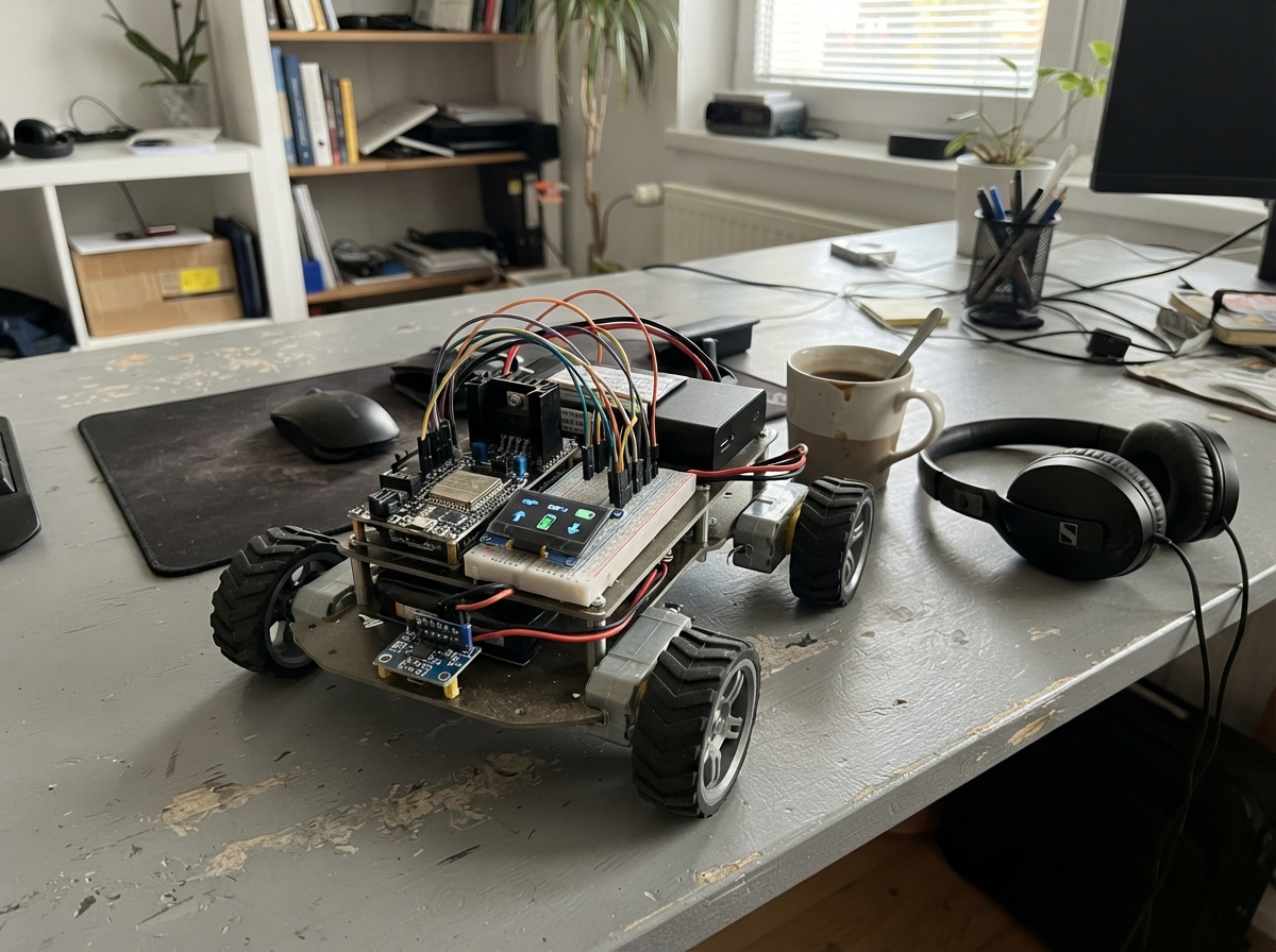
Build a four-wheel rover that responds to tablet commands over WiFi, with obstacle avoidance capability. The Rover 5 platform combines four independent motors with an ESP32 microcontroller, a high-current motor driver, and a time-of-flight distance sensor to create a responsive mobile robot that can be controlled through a web interface or operate autonomously.
This guide provides a complete wiring diagram, parts list, and step-by-step assembly instructions for integrating the IBT-2 motor driver, VL53L0X sensor, and LiPo power system. You'll learn how to configure motor control signals, implement battery monitoring, and upload firmware that enables both manual tablet control and automatic obstacle detection.
Wiring diagram
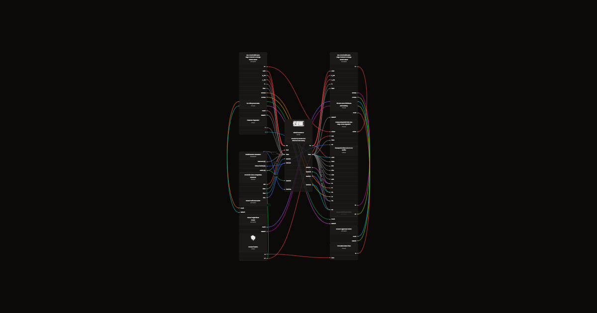
Gather all the parts
Assemble it in 6 steps
1. Mount the robot electronics
Mount two IBT-2 drivers and ESP32 securely above the Rover 5. Fix the distance sensor at the front, facing straight ahead. Use a VL53L0X breakout that accepts 3.3V, not a bare sensor chip. Secure the Samsung SM-T700 low and centrally; its browser is the controller, not the robot's motor controller.
- This detects front obstacles only, not stairs, side obstacles or rear obstacles. Use on a flat enclosed floor away from people and pets.
2. Connect the four motors
Connect both left motors in parallel to left M+ and M-, and both right motors to right M+ and M-. Leave all encoder leads unplugged and individually insulated. Use 18AWG motor wires and screw terminals, never a breadboard for motor current.
3. Wire the control signals
Wire GPIO25/26 through buffer channels 1/2 to left RPWM/LPWM; GPIO27/33 through channels 3/4 to right RPWM/LPWM. Buffer VCC goes to 5V, GND and all OE pins to ground. Add one 10k resistor from each buffer input to ground. Place the 100nF capacitor across buffer VCC and ground. Driver VCC and enable inputs go to 5V; all logic and power grounds join. Sensor VIN goes to 3V3, SDA to GPIO21 (data), SCL to GPIO22 (clock).
4. Install regulated LiPo motor power
Remove the NiMH holder. Use the battery female XT60 with a matching male XT60 pigtail, observing molded + and - markings; solder only the disconnected robot-side pigtail and insulate each joint. Positive goes through the existing 7.5A fuse close to the connector, then a switch rated 10A at 24V DC, then regulator VIN. Battery negative and regulator GND go to shared ground. Regulator VOUT goes to both driver B+ terminals. Choose Pololu D24V150F6 (#2882), fixed 6V: deliberately below the 7.2V motor rating, with reduced top speed. Do not substitute the 7.5V version. Use 18AWG power wires, screw terminals and free airflow. USB bank still powers ESP32 and 5V logic; disconnect it before computer USB.
- Never connect the LiPo directly to motors or ESP32. Never carry motor current through a breadboard.
- Unplug the pack to charge outside the robot using a 3S LiPo balance charger and both required charger connectors. Never charge unattended; do not use a swollen or damaged pack.
5. Wire and verify battery shutdown
Wire 47k resistor from switched battery positive to GPIO34, and 10k from GPIO34 to ground. This reduces 12.6V to about 2.21V for measurement. Wire GPIO32 through 4.7k to 2N3904 base, 100k from base to ground, emitter to ground and collector to regulator EN. Verify transistor package pin labels against its datasheet, not its orientation. EN has an internal 5V pullup: never connect it directly to ESP32. With motor outputs disconnected, confirm VOUT is about 6V and displayed battery voltage agrees with a multimeter; do not operate if reading is wrong. Firmware latches regulator off below 10.8V, including missing battery sensing. After shutdown unplug battery and recharge; never reset just to keep driving. Power logic first, motors second.
- Pack-voltage cutoff is not individual-cell protection. Use only a balanced healthy pack; check each cell with the balance charger before and after use. Do not use a pack with an unusually low cell.
- Disconnect battery after use even after shutdown; electronics still draw a small current. The cutoff depends on working firmware and correct sensing, not an independent safety-rated protection circuit.
6. Test with tracks off the floor
With tracks raised and motor switch off, check every connection. Power logic first, then motors. Test briefly at low speed. For Forward all four motors must move their tracks forward. If a motor disagrees, power everything off and swap only that motor's two leads. Test the front sensor using a large box before allowing autonomous travel. Reverse and turns are not obstacle-protected.
Review all connections
1. Connections between "battery" and "ESP32"
2. Connections between "fuse" and "ESP32"
3. Connections between "usb" and "ESP32"
4. Connections between "buffer" and "ESP32"
5. Connections between "range" and "ESP32"
6. Connections between "left" and "ESP32"
7. Connections between "r1" and "ESP32"
8. Connections between "r2" and "ESP32"
9. Connections between "right" and "ESP32"
10. Connections between "r3" and "ESP32"
11. Connections between "r4" and "ESP32"
12. Connections between "decouple" and "ESP32"
13. Connections between "switch" and "ESP32"
14. Connections between "regulator" and "ESP32"
15. Connections between "cutoff" and "ESP32"
16. Connections between "base" and "ESP32"
17. Connections between "basepull" and "ESP32"
18. Connections between "battery_upper" and "ESP32"
19. Connections between "battery_lower" and "ESP32"
Deploy the firmware
#include <Arduino.h>
#include <WiFi.h>
#include <WebServer.h>
#include <Wire.h>
#include <VL53L0X.h>
WebServer server(80); VL53L0X sensor;
const int pins[]={25,26,27,33};
float batteryV=0; bool lowBattery=false; unsigned long batteryRead=0;
bool ready=false,automatic=false; char command='s'; unsigned long heartbeat=0,lastRead=0,turnUntil=0; int distanceMm=0; bool valid=false;
const char page[] PROGMEM=R"HTML(<!doctype html><html><head><meta name="viewport" content="width=device-width,initial-scale=1"><title>Rover 5</title><style>body{font:24px sans-serif;text-align:center}button{font-size:24px;padding:22px;margin:7px;touch-action:none}</style></head><body><h2>Rover 5</h2><p>Hold a direction to drive</p><button ontouchstart="go('f',event)" onmousedown="go('f',event)">Forward</button><br><button ontouchstart="go('l',event)" onmousedown="go('l',event)">Left</button><button onclick="stop()">STOP</button><button ontouchstart="go('r',event)" onmousedown="go('r',event)">Right</button><br><button ontouchstart="go('b',event)" onmousedown="go('b',event)">Reverse</button><br><button onclick="autoMode()">Auto avoid</button><p>Auto runs only while this page stays connected.</p><pre id="status"></pre><script>
var c='s',timer=null;function send(){var x=new XMLHttpRequest();x.open('GET','/cmd?c='+c,true);x.send()}function go(v,e){e.preventDefault();c=v;send()}function stop(){c='s';send()}function autoMode(){c='a';send()}document.addEventListener('touchend',function(){if(c!='a')stop()});document.addEventListener('mouseup',function(){if(c!='a')stop()});window.onblur=stop;document.addEventListener('visibilitychange',function(){if(document.hidden)stop()});setInterval(function(){if(!document.hidden)send()},200);setInterval(function(){var x=new XMLHttpRequest();x.onload=function(){document.getElementById('status').textContent=x.responseText};x.open('GET','/status',true);x.send()},700);
</script></body></html>)HTML";
void rawStop(){for(int i=0;i<4;i++) analogWrite(pins[i],0);}
void drive(int left,int right){static int oldL=0,oldR=0; static unsigned long waitUntil=0;unsigned long now=millis();if((oldL*left<0)||(oldR*right<0)){rawStop();oldL=oldR=0;waitUntil=now+180;}if((long)(now-waitUntil)<0)return;analogWrite(pins[0],left>0?left:0);analogWrite(pins[1],left<0?-left:0);analogWrite(pins[2],right>0?right:0);analogWrite(pins[3],right<0?-right:0);oldL=left;oldR=right;}
void setup(){Serial.begin(115200);pinMode(32,OUTPUT);digitalWrite(32,HIGH);analogSetPinAttenuation(34,ADC_11db);for(int p:pins){pinMode(p,OUTPUT);digitalWrite(p,LOW);}Wire.begin(21,22);sensor.setTimeout(100);ready=sensor.init();if(ready)sensor.startContinuous(50);WiFi.softAP("Rover5-Control","Rover5Drive!");server.on("/",[]{server.send_P(200,"text/html",page);});server.on("/cmd",[]{String c=server.arg("c");if(c.length()==1&&strchr("sflrba",c[0])){command=c[0];automatic=command=='a';heartbeat=millis();}server.send(200,"text/plain","OK");});server.on("/status",[]{server.send(200,"text/plain",String(lowBattery?"LOW BATTERY - disconnect and recharge":(automatic?"AUTO":"MANUAL"))+"\nBattery: "+String(batteryV,2)+" V"+"\nFront: "+(valid?String(distanceMm)+" mm":"sensor unavailable - stopped"));});server.begin();Serial.println("Join Rover5-Control, open http://192.168.4.1");}
void loop(){server.handleClient();unsigned long now=millis();if(now-batteryRead>=100){batteryRead=now;uint32_t total=0;for(int i=0;i<16;i++)total+=analogReadMilliVolts(34);batteryV=(total/16.0f)*5.7f/1000.0f;if(batteryV<10.8f)lowBattery=true;digitalWrite(32,lowBattery?HIGH:LOW);}if(lowBattery){rawStop();command='s';automatic=false;return;}if(ready&&now-lastRead>=60){lastRead=now;distanceMm=sensor.readRangeContinuousMillimeters();valid=!sensor.timeoutOccurred()&&distanceMm>0&&distanceMm<8190;}if(now-heartbeat>900||!ready||!valid){command='s';automatic=false;drive(0,0);return;}int l=0,r=0;const int speed=100;if(automatic){if(distanceMm<350&&turnUntil==0)turnUntil=now+650;if(turnUntil&&(long)(now-turnUntil)<0){l=speed;r=-speed;}else{turnUntil=0;if(distanceMm>=350)l=r=speed;}}else{turnUntil=0;switch(command){case 'f':if(distanceMm>=350)l=r=speed;break;case 'b':l=r=-speed;break;case 'l':l=-speed;r=speed;break;case 'r':l=speed;r=-speed;break;}}drive(l,r);}

// Battery divider junction verified on ADC1 GPIO34.
Remix this project
Make it yours in one click
Open a full copy of this project in your own Schematik workspace, diagram, code, parts, and assembly steps included. Swap the sensor, add features, or redesign the whole thing with AI. The author's original stays untouched.