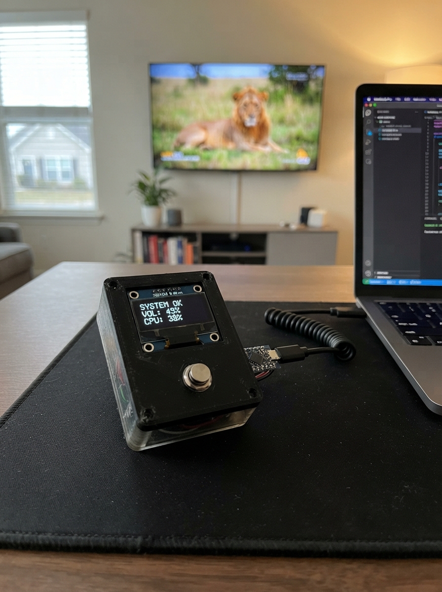
Build a compact USB control pad with eight programmable buttons and an OLED display for desktop shortcuts and media controls. The ESP32 microcontroller handles button debouncing and HID communication, while the SSD1306 display shows which action was triggered. This guide includes a wiring diagram, complete parts list, pre-written firmware, and step-by-step assembly instructions to get the pad working as a plug-and-play USB device.
The first four buttons control volume and playback, while buttons five through eight execute copy, paste, undo, and screenshot commands. The firmware implements software debouncing to ensure reliable button presses, and the display provides visual feedback for each action. Once assembled and connected via USB, the pad works with any computer that supports standard HID keyboards and media controls.
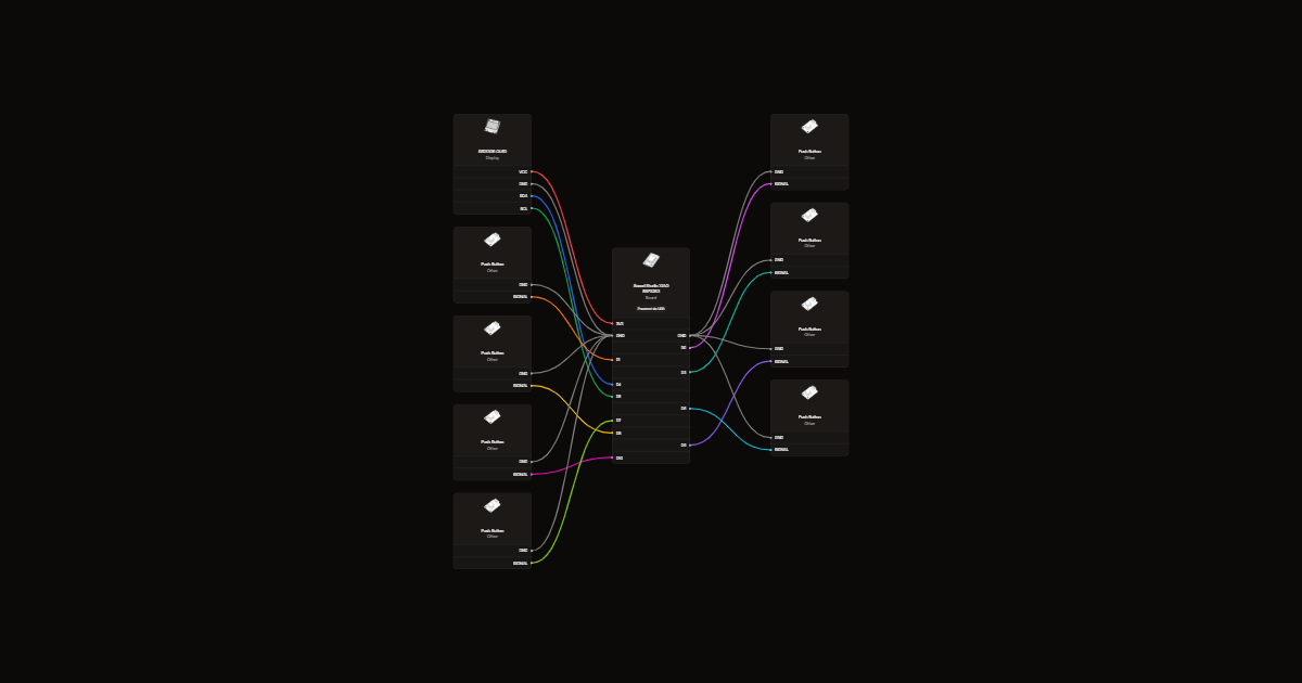
Wiring diagram
Gather all the parts
Assemble it in 4 steps
1. Prepare the board and buttons
Use an ESP32-S3-DevKitC-1 and eight normally-open momentary buttons. Disconnect USB before wiring. Arrange the buttons in two rows of four: Volume up, Volume down, Mute, Play/pause; Copy, Paste, Undo, Screenshot.
- On a four-leg tactile switch, the two legs on each side are already joined. Use terminals on opposite electrical sides; check with a continuity meter if unsure.
2. Connect the display
Connect OLED VCC to 3V3 (power), GND to GND (ground), SDA to GPIO8 (data), and SCL to GPIO9 (clock).
- Check printed pin labels rather than pin order. Swapped VCC and GND can damage the OLED. Use 3.3 V, not 5 V, to keep the data lines safe.
3. Connect the eight buttons
Connect one terminal of every button to GND. Connect the other terminals for buttons 1 through 8 to GPIO1, GPIO2, GPIO4, GPIO5, GPIO6, GPIO7, GPIO10, GPIO11 respectively. Internal pull-up resistors keep the inputs steady; a press connects the input to ground.
4. Check the wiring and USB connection
Check for loose wires and shorts. Use a USB data cable. The port marked USB is the native keyboard connection; the USB-to-UART port is for programming and will not send keyboard actions. You may use the UART port for deployment, then connect the native USB port to your Windows computer.
- Shortcuts affect the focused window. Screenshot opens the Windows area-selection tool. Each press sends one action; holding a button does not repeat it.
- The display shows the last requested action, not the computer's actual volume or playback state.
Review all connections
1. Connections between "oled" and "ESP32"
2. Connections between "key1" and "ESP32"
3. Connections between "key2" and "ESP32"
4. Connections between "key3" and "ESP32"
5. Connections between "key4" and "ESP32"
6. Connections between "key5" and "ESP32"
7. Connections between "key6" and "ESP32"
8. Connections between "key7" and "ESP32"
9. Connections between "key8" and "ESP32"
Deploy the firmware
#include <Arduino.h>
#include <Wire.h>
#include <Adafruit_GFX.h>
#include <Adafruit_SSD1306.h>
#include <USB.h>
#include <USBHIDKeyboard.h>
#include <USBHIDConsumerControl.h>
USBHIDKeyboard keyboard;
USBHIDConsumerControl media;
Adafruit_SSD1306 screen(128,64,&Wire,-1);
const uint8_t pins[]={1,2,4,5,6,7,10,11};
const char* labels[]={"Volume up","Volume down","Mute","Play / pause","Copy","Paste","Undo","Screenshot"};
bool raw[8],stable[8],displayOK=false;
uint32_t changed[8];
void show(const char* action){
 if(!displayOK)return;
 screen.clearDisplay(); screen.setTextColor(SSD1306_WHITE);
 screen.setTextSize(1);screen.setCursor(0,0);screen.println("USB DESKTOP PAD");
 screen.setCursor(0,22);screen.println(action);
 screen.setCursor(0,45);screen.println("1-4 Media");screen.println("5-8 Shortcuts");screen.display();
}
void action(uint8_t i){
 if(i<4){
 const uint16_t codes[]={CONSUMER_CONTROL_VOLUME_INCREMENT,CONSUMER_CONTROL_VOLUME_DECREMENT,CONSUMER_CONTROL_MUTE,CONSUMER_CONTROL_PLAY_PAUSE};
 media.press(codes[i]);delay(15);media.release();
 }else{
 if(i==7){keyboard.press(KEY_LEFT_GUI);keyboard.press(KEY_LEFT_SHIFT);keyboard.press('s');}
 else{keyboard.press(KEY_LEFT_CTRL);keyboard.press(i==4?'c':i==5?'v':'z');}
 delay(15);keyboard.releaseAll();
 }
 show(labels[i]);
}
void setup(){
 for(uint8_t i=0;i<8;i++){pinMode(pins[i],INPUT_PULLUP);raw[i]=stable[i]=digitalRead(pins[i]);changed[i]=millis();}
 keyboard.begin();media.begin();USB.begin();
 Wire.begin(8,9);
 displayOK=screen.begin(SSD1306_SWITCHCAPVCC,0x3C,true,false);
 show("Ready - Windows");
}
void loop(){
 uint32_t now=millis();
 for(uint8_t i=0;i<8;i++){
 bool r=digitalRead(pins[i]);
 if(r!=raw[i]){raw[i]=r;changed[i]=now;}
 if(now-changed[i]>=25 && stable[i]!=raw[i]){stable[i]=raw[i];if(!stable[i])action(i);}
 }
 delay(1);
}
Remix this project
Make it yours in one click
Open a full copy of this project in your own Schematik workspace, diagram, code, parts, and assembly steps included. Swap the sensor, add features, or redesign the whole thing with AI. The author's original stays untouched.