Community project
Portable Morse Radio Communicator
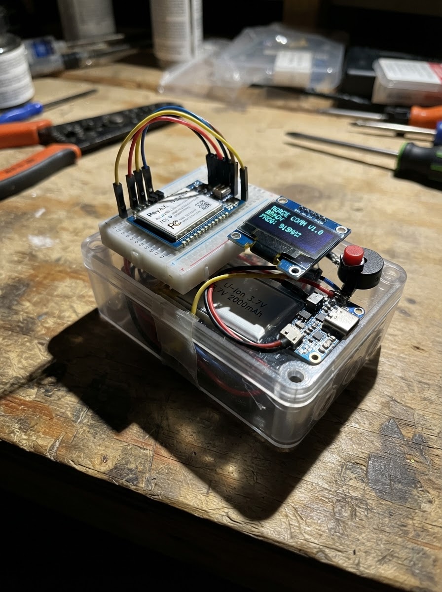
Build a portable LoRa-based Morse code communicator that lets operators send and receive Morse over long distances using the US915 frequency band. This project combines an ESP32 microcontroller with a Reyax RYLR998 LoRa transceiver, OLED display, push-button key, and piezo buzzer in a battery-powered enclosure, creating a compact radio station for field communication.
This guide provides a complete parts list, wiring diagram, step-by-step assembly instructions, and ready-to-flash firmware. Builders will learn how to interface the LoRa module with the ESP32, implement debounced key input handling, drive the OLED display for status feedback, and manage audio output for Morse reception. The rechargeable battery system with integrated charging support keeps the communicator operational in the field.
Wiring diagram

Gather all the parts
Assemble it in 7 steps
1. Prepare the portable enclosure
Use a non-metal walkie-talkie-sized plastic enclosure. Make openings for the USB-C socket, one large momentary pushbutton, the OLED screen, and the buzzer sound hole. Mount the ESP32, charger board, radio module, screen, and buzzer so the radio module’s integral antenna end has at least 10 mm of clear space from the battery and other wiring.
- Use short pieces of insulated wire for the radio connections.
- Place the battery away from the radio antenna end.
- Do not put the unit in a metal enclosure; metal blocks the radio signal.
- Do not drill, crush, bend sharply, or puncture the battery — a damaged lithium battery can catch fire.
- Do not cover, cut, replace, or operate the radio module without its approved integral antenna; that can create an illegal transmitter and can damage the module.
2. Connect the rechargeable battery
With no USB cable connected, connect battery_1 BAT+ to charger_3v3 BAT (battery positive) and battery_1 BAT- to charger_3v3 GND (ground). Insulate both joints individually with heat-shrink tubing or electrical tape.
- Red normally means battery positive and black normally means battery negative.
- Make these connections before connecting the rest of the electronics.
- Make sure the battery positive and negative wires are not swapped — swapped battery power can damage the charger board or overheat the battery.
- Use only a protected single-cell 3.7 V LiPo/Li-ion battery; do not connect a 9 V battery, AA holder, or two cells in series.
3. Make the shared power wires
Connect charger_3v3 3V3 to the ESP32 3V3 pin, radio_915 VDD, and oled_1 VCC (power). Connect charger_3v3 GND to the ESP32 GND pin, radio_915 GND, oled_1 GND, morse_key GND, and buzzer_1 Lead 2 (ground). All ground wires must meet on this shared ground connection.
- Use a small soldered ground bus or a common breadboard ground row during testing.
- The 3V3 label is important: do not use the ESP32 VIN or 5V pin for these parts.
- Do not connect the charger’s 3V3 output to the ESP32 VIN/5V pin — that can make the ESP32 unreliable or damage 3.3 V parts.
- Make sure VCC/VDD and GND are not swapped on the radio and screen — swapped power can damage them.
4. Wire the radio module
Connect radio_915 RXD to ESP32 GPIO17 (data from the ESP32 to the radio). Connect radio_915 TXD to ESP32 GPIO16 (data from the radio to the ESP32). Keep these two data wires short and away from the antenna end.
- RX and TX cross over: the radio’s RXD goes to the ESP32 transmit pin GPIO17, while the radio’s TXD goes to the ESP32 receive pin GPIO16.
- Use only the supplied US915 certified module and its integral approved antenna.
- Never connect either radio data pin to 5 V — both use 3.3 V signals.
- Do not use a different antenna, add an amplifier, or raise the configured transmit power; those changes can invalidate the FCC-certified radio configuration.
5. Wire the screen and Morse key
Connect oled_1 SDA to ESP32 GPIO21 (screen data) and oled_1 SCL to ESP32 GPIO22 (screen clock). Connect the free morse_key SIGNAL terminal to ESP32 GPIO27 (key signal). The other key terminal is already connected to ground in the shared-power step.
- A four-pin OLED normally prints VCC, GND, SCL, and SDA beside the pins; follow those printed labels, not just wire order.
- The pushbutton has no positive or negative side.
- Make sure VCC and GND are not swapped on the OLED — swapped power can damage the screen.
- Do not use GPIO0, GPIO2, GPIO5, GPIO12, or GPIO15 for the key because those pins affect ESP32 startup.
6. Wire the Morse sounder
Connect buzzer_1 Lead 1 to ESP32 GPIO25 (tone signal). Its other lead is already connected to the shared GND connection. If your piezo has a red lead or a plus mark, use that lead as Lead 1.
- A passive piezo is required because the firmware creates the 700 Hz Morse tone.
- If the buzzer is very loud, cover part of its sound opening with tape rather than changing the wiring.
- Do not connect the buzzer directly to the battery; it belongs on GPIO25 and GND.
7. Inspect and charge before closing
Check every connection against the diagram, especially all 3V3 and GND wires. Plug a USB-C cable into charger_3v3 to charge the battery; after wiring is confirmed, use a USB cable connected to the ESP32 for programming and press Deploy in Schematik. Build a second identical unit using the same firmware and radio settings to exchange Morse.
- The screen should show LISTEN when the unit starts; holding the key should show SENDING and sound a tone.
- Test the pair first a few feet apart, then increase separation in an open outdoor area.
- Do not attempt to charge a swollen, hot, punctured, or wet battery.
- If any board gets hot, unplug both USB cables immediately and recheck power polarity before trying again.
Review all connections
1. Connections between "charger_3v3" and "ESP32"
2. Connections between "battery_1" and "ESP32"
3. Connections between "radio_915" and "ESP32"
4. Connections between "oled_1" and "ESP32"
5. Connections between "morse_key" and "ESP32"
6. Connections between "buzzer_1" and "ESP32"
Deploy the firmware
#include <Arduino.h>
#include <Wire.h>
#include <Adafruit_GFX.h>
#include <Adafruit_SSD1306.h>


// Forward declarations
void setTone(bool enabled);
void showState(const String &state, const String &detail);
void sendCommand(const String &command, uint32_t waitMs);
void configureRadio();
void sendKeyPacket(char packet);
void handleReceivedLine(const String &line);
void pollRadio();
void pollKey();

constexpr int RADIO_RX_PIN = 16;
constexpr int RADIO_TX_PIN = 17;
constexpr int OLED_SDA_PIN = 21;
constexpr int OLED_SCL_PIN = 22;
constexpr int KEY_PIN = 27;
constexpr int BUZZER_PIN = 25;
constexpr uint32_t RADIO_BAUD = 115200;
constexpr uint16_t TONE_HZ = 700;
constexpr uint32_t DEBOUNCE_MS = 20;
constexpr uint32_t RECEIVE_TONE_TIMEOUT_MS = 2500;

HardwareSerial radioSerial(2);
Adafruit_SSD1306 display(128, 64, &Wire, -1);

bool lastRawKey = HIGH;
bool stableKey = HIGH;
uint32_t rawChangedAt = 0;
bool remoteKeyDown = false;
uint32_t remoteLastPacketAt = 0;
String radioLine;
String shownState;

void setTone(bool enabled) {
  if (enabled) {
    tone(BUZZER_PIN, TONE_HZ);
  } else {
    noTone(BUZZER_PIN);
  }
}

void showState(const String &state, const String &detail) {
  String combined = state + "\n" + detail;
  if (combined == shownState) {
    return;
  }
  shownState = combined;
  display.clearDisplay();
  display.setTextColor(SSD1306_WHITE);
  display.setTextSize(2);
  display.setCursor(0, 0);
  display.println("MORSE 915");
  display.setTextSize(2);
  display.setCursor(0, 28);
  display.println(state);
  display.setTextSize(1);
  display.setCursor(0, 54);
  display.println(detail);
  display.display();
}

void sendCommand(const String &command, uint32_t waitMs = 120) {
  radioSerial.println(command);
  delay(waitMs);
  while (radioSerial.available()) {
    radioSerial.read();
  }
}

void configureRadio() {
  sendCommand("AT");
  sendCommand("AT+ADDRESS=1");
  sendCommand("AT+NETWORKID=18");
  sendCommand("AT+BAND=915000000");
  sendCommand("AT+PARAMETER=12,7,1,4");
  sendCommand("AT+CRFOP=14");
}

void sendKeyPacket(char packet) {
  String command = String("AT+SEND=2,1,") + packet;
  radioSerial.println(command);
}

void handleReceivedLine(const String &line) {
  int firstComma = line.indexOf(',');
  int secondComma = line.indexOf(',', firstComma + 1);
  int thirdComma = line.indexOf(',', secondComma + 1);
  if (!line.startsWith("+RCV=") || firstComma < 0 || secondComma < 0 || thirdComma < 0) {
    return;
  }

  String payload = line.substring(secondComma + 1, thirdComma);
  if (payload.length() != 1) {
    return;
  }

  char packet = payload.charAt(0);
  if (packet == 'K') {
    remoteKeyDown = true;
    remoteLastPacketAt = millis();
    setTone(true);
    showState("RECEIVE", "other key is down");
  } else if (packet == 'U') {
    remoteKeyDown = false;
    setTone(false);
    showState("LISTEN", "ready for Morse");
  }
}

void pollRadio() {
  while (radioSerial.available()) {
    char c = static_cast<char>(radioSerial.read());
    if (c == '\n' || c == '\r') {
      if (radioLine.length() > 0) {
        handleReceivedLine(radioLine);
        radioLine = "";
      }
    } else if (radioLine.length() < 120) {
      radioLine += c;
    } else {
      radioLine = "";
    }
  }
}

void pollKey() {
  bool rawKey = digitalRead(KEY_PIN);
  if (rawKey != lastRawKey) {
    lastRawKey = rawKey;
    rawChangedAt = millis();
  }

  if ((millis() - rawChangedAt) >= DEBOUNCE_MS && rawKey != stableKey) {
    stableKey = rawKey;
    bool pressed = (stableKey == LOW);
    if (pressed) {
      remoteKeyDown = false;
      setTone(true);
      sendKeyPacket('K');
      showState("SENDING", "hold key for tone");
    } else {
      setTone(false);
      sendKeyPacket('U');
      showState("LISTEN", "ready for Morse");
    }
  }
}

void setup() {
  pinMode(KEY_PIN, INPUT_PULLUP);
  pinMode(BUZZER_PIN, OUTPUT);
  noTone(BUZZER_PIN);

  Wire.begin(OLED_SDA_PIN, OLED_SCL_PIN);
  display.begin(SSD1306_SWITCHCAPVCC, 0x3C);
  display.clearDisplay();
  display.display();

  radioSerial.begin(RADIO_BAUD, SERIAL_8N1, RADIO_RX_PIN, RADIO_TX_PIN);
  showState("STARTING", "configuring radio");
  configureRadio();
  showState("LISTEN", "ready for Morse");
}

void loop() {
  pollKey();
  pollRadio();

  if (remoteKeyDown && (millis() - remoteLastPacketAt > RECEIVE_TONE_TIMEOUT_MS)) {
    remoteKeyDown = false;
    if (stableKey == HIGH) {
      setTone(false);
      showState("LISTEN", "signal timeout");
    }
  }
}
Remix this project
Make it yours in one click
Open a full copy of this project in your own Schematik workspace — diagram, code, parts, and assembly steps included. Swap the sensor, add features, or redesign the whole thing with AI. The author's original stays untouched.