Community project
Reloj Para Una Esp32-32 N4 Yellowcard Cyd 3
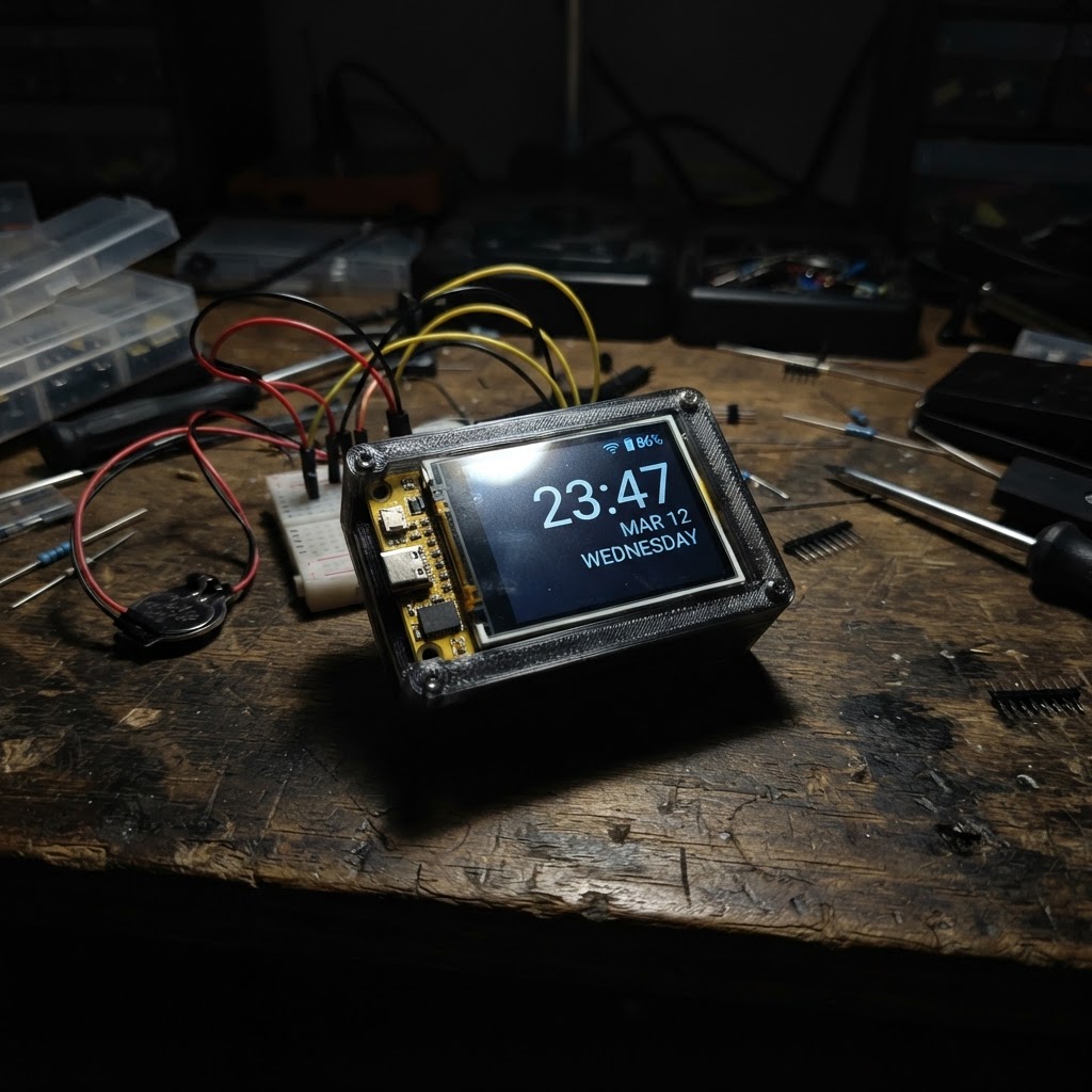
This project turns an ESP32-32 N4 Yellowcard CYD into a networked clock that displays the current time and date on its 3-inch ILI9341 touchscreen display. The clock automatically synchronizes with NTP servers over WiFi and adjusts for Spanish peninsula timezone rules, including daylight saving time transitions.
Builders will receive a complete wiring diagram showing how to connect the CYD's display pins to the ESP32, a parts list, and ready-to-deploy firmware that handles WiFi connectivity, time synchronization, and screen rendering. Assembly involves powering the CYD via USB, verifying display orientation, and uploading the firmware to the microcontroller.
Wiring diagram
Assemble it in 3 steps
1. Alimenta la CYD por USB
Conecta un cable USB de datos al conector USB de la placa ESP32-32 N4 Yellow Card CYD 3.2 pulgadas. No hace falta añadir módulos ni cables externos: pantalla, panel táctil y Wi‑Fi ya forman parte de la placa.
- Usa una fuente USB estable de 5 V.
- El reloj se conectará a la red Wi‑Fi indicada al iniciarse.
- No conectes una fuente externa a los pines de 3,3 V mientras la placa está alimentada por USB.
2. Comprueba la orientación de la pantalla
Coloca la placa de manera que puedas leer la pantalla en horizontal. El firmware muestra el título, la hora grande, la fecha y el estado de conexión Wi‑Fi.
- La primera sincronización puede tardar unos segundos tras arrancar.
3. Despliega el firmware
Con la placa conectada por USB, usa el botón Deploy de Schematik para compilar y cargar el reloj. Después de conectarse al Wi‑Fi, la hora se ajusta automáticamente mediante servidores de hora de Internet.
- La zona horaria configurada es España peninsular y cambia automáticamente entre horario de invierno y verano.
- La contraseña de Wi‑Fi queda incorporada en el firmware; evita compartir el proyecto compilado si no quieres divulgarla.
Deploy the firmware
#include <Arduino.h>
#include <WiFi.h>
#include <time.h>
#include <Arduino_GFX_Library.h>

// Colores RGB565 explícitos: también permiten compilar en el simulador del navegador.
constexpr uint16_t BLACK = 0x0000;
constexpr uint16_t WHITE = 0xFFFF;
constexpr uint16_t CYAN = 0x07FF;
constexpr uint16_t GREEN = 0x07E0;
constexpr uint16_t YELLOW = 0xFFE0;

// Red Wi-Fi configurada para este reloj.

// Forward declarations
void centerText(const String &text, int y, uint8_t size, uint16_t color);
void drawStaticScreen();
void drawConnectionStatus(bool connected);
void connectWifi();

const char *WIFI_SSID = "Diversion.con.banderas";
const char *WIFI_PASSWORD = "Trustn01";

// Hora de España peninsular: cambia automáticamente entre CET y CEST.
const char *TIMEZONE = "CET-1CEST,M3.5.0/2,M10.5.0/3";
const char *NTP_SERVER_1 = "pool.ntp.org";
const char *NTP_SERVER_2 = "time.google.com";

constexpr int TFT_SCLK = 14;
constexpr int TFT_MOSI = 13;
constexpr int TFT_MISO = 12;
constexpr int TFT_CS = 15;
constexpr int TFT_DC = 2;
constexpr int TFT_RST = -1;  // El reset del ILI9341 está unido a EN en esta CYD.
constexpr int TFT_BL = 21;

Arduino_DataBus *bus = new Arduino_ESP32SPI(TFT_DC, TFT_CS, TFT_SCLK, TFT_MOSI, TFT_MISO);
Arduino_GFX *display = new Arduino_ILI9341(bus, TFT_RST, 1, false);

String lastTimeText;
String lastDateText;
bool lastWifiConnected = false;
unsigned long lastWifiAttempt = 0;

void centerText(const String &text, int y, uint8_t size, uint16_t color) {
  display->setTextSize(size);
  display->setTextColor(color);
  int16_t x1, y1;
  uint16_t w, h;
  display->getTextBounds(text, 0, y, &x1, &y1, &w, &h);
  display->setCursor((display->width() - w) / 2, y);
  display->print(text);
}

void drawStaticScreen() {
  display->fillScreen(BLACK);
  display->fillRect(0, 0, display->width(), 30, 0x001F);
  centerText("RELOJ WIFI", 7, 2, WHITE);
  display->drawRoundRect(8, 42, display->width() - 16, 86, 8, CYAN);
  display->drawRoundRect(8, 143, display->width() - 16, 47, 8, 0x7BEF);
}

void drawConnectionStatus(bool connected) {
  display->fillRect(10, 200, display->width() - 20, 30, BLACK);
  if (connected) {
    centerText("Wi-Fi conectado", 207, 1, GREEN);
  } else {
    centerText("Conectando Wi-Fi...", 207, 1, YELLOW);
  }
}

void connectWifi() {
  WiFi.mode(WIFI_STA);
  WiFi.begin(WIFI_SSID, WIFI_PASSWORD);
  lastWifiAttempt = millis();
}

void setup() {
  pinMode(TFT_BL, OUTPUT);
  digitalWrite(TFT_BL, HIGH);

  display->begin();
  display->setRotation(1); // Pantalla en horizontal, 320 x 240.
  drawStaticScreen();
  drawConnectionStatus(false);

  connectWifi();
  configTzTime(TIMEZONE, NTP_SERVER_1, NTP_SERVER_2);
}

void loop() {
  const bool wifiConnected = WiFi.status() == WL_CONNECTED;
  if (!wifiConnected && millis() - lastWifiAttempt > 15000UL) {
    WiFi.disconnect();
    connectWifi();
  }

  if (wifiConnected != lastWifiConnected) {
    drawConnectionStatus(wifiConnected);
    lastWifiConnected = wifiConnected;
  }

  tm now;
  if (!getLocalTime(&now, 10)) {
    delay(200);
    return;
  }

  char timeBuffer[12];
  char dateBuffer[32];
  strftime(timeBuffer, sizeof(timeBuffer), "%H:%M:%S", &now);
  strftime(dateBuffer, sizeof(dateBuffer), "%A, %d/%m/%Y", &now);
  String timeText(timeBuffer);
  String dateText(dateBuffer);

  // Solo se repintan estas zonas cuando cambia lo que se ve en pantalla.
  if (timeText != lastTimeText) {
    display->fillRect(10, 44, display->width() - 20, 82, BLACK);
    centerText(timeText, 64, 5, WHITE);
    lastTimeText = timeText;
  }
  if (dateText != lastDateText) {
    display->fillRect(10, 145, display->width() - 20, 43, BLACK);
    centerText(dateText, 160, 1, 0xFFE0);
    lastDateText = dateText;
  }

  delay(100);
}
Remix this project
Make it yours in one click
Open a full copy of this project in your own Schematik workspace — diagram, code, parts, and assembly steps included. Swap the sensor, add features, or redesign the whole thing with AI. The author's original stays untouched.