Community project
RFID Music Assistant Controller
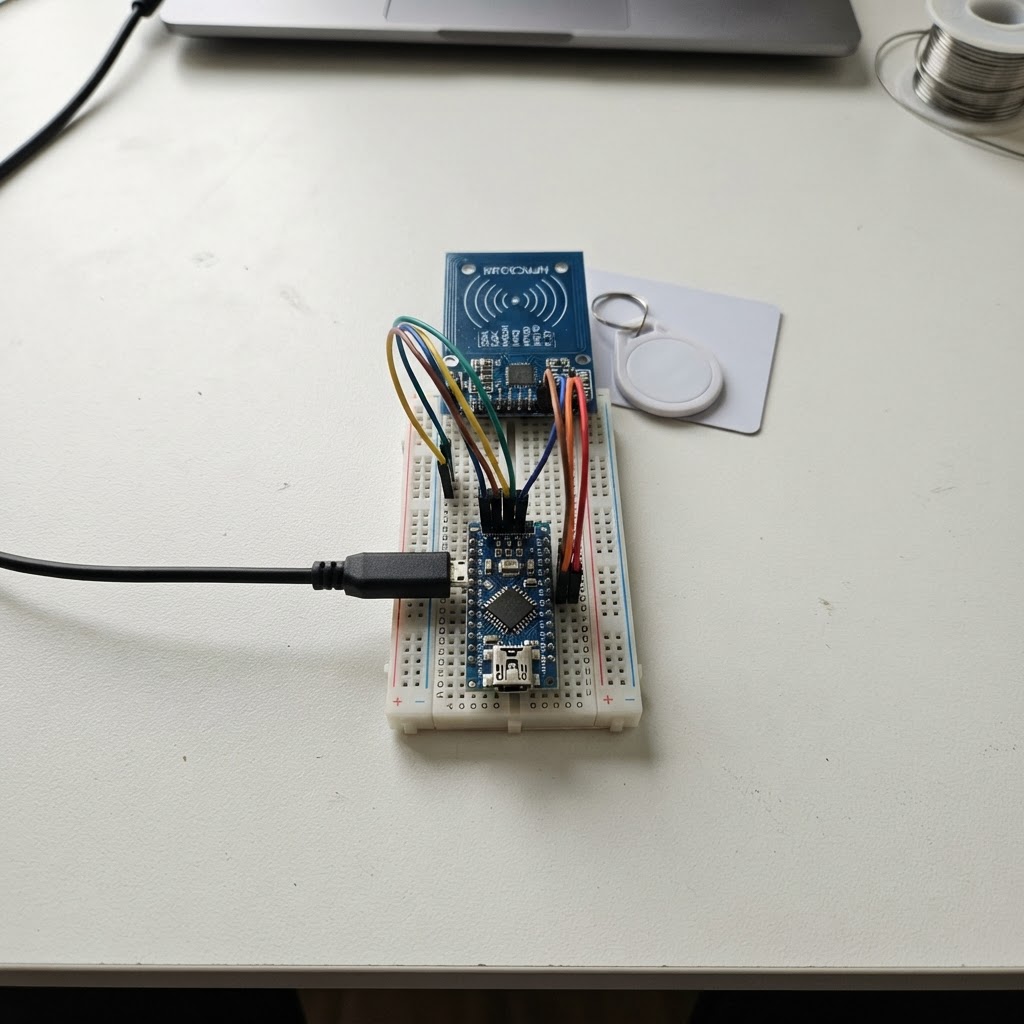
This project turns RFID tags into wireless music controls by connecting an MFRC522 RFID reader to an ESP32 microcontroller. When a tag is scanned, the device sends the tag's unique ID over WiFi to Home Assistant via MQTT, enabling automation routines that can play, pause, skip, or switch playlists based on which tag is presented to the reader.
The guide provides a complete parts list, wiring diagram showing all five connections between the MFRC522 and ESP32, step-by-step assembly instructions, and ready-to-use firmware that handles WiFi connection, MQTT communication, and tag detection. Readers will learn how to configure WiFi credentials and MQTT settings, then deploy a smart home controller that works with any Home Assistant setup.
Wiring diagram

Gather all the parts
Assemble it in 4 steps
1. Keep the reader unpowered while wiring
Unplug the ESP32-C3 from USB before connecting anything. Put the REES52 RC522 module beside the board with its printed pin labels visible.
- The RC522 pin marked SDA is its select wire, not the same kind of SDA wire used by some other sensors.
- Do not connect the RC522 VCC pin to 5V — this reader is a 3.3 V part and 5V can damage it.
2. Connect power and ground
Connect RC522 VCC to the ESP32-C3 3V3 pin (power). Connect RC522 GND to any ESP32-C3 GND pin (ground). These two wires let both boards share the same safe power supply.
- Use red for the 3V3 wire and black for the GND wire if you have coloured jumper wires.
- Make sure VCC and GND are not swapped — swapped power can damage the RFID reader.
3. Connect the four data wires
Connect RC522 SCK to ESP32-C3 GPIO4 (clock). Connect RC522 MOSI to GPIO6 (data to the reader). Connect RC522 MISO to GPIO5 (data back from the reader). Connect RC522 SDA to GPIO7 (select signal).
- Follow the printed GPIO names or numbers on your particular ESP32-C3 board, not just the physical position along the header.
- Keep these four wires short and firmly seated so the reader can reliably hear the card.
- Do not use the RC522 SDA pin as an I2C wire; on this module it is the reader-select signal.
4. Connect the reset wire
Connect RC522 RST to ESP32-C3 GPIO3 (reset control). Check that no loose wire can touch a neighbouring pin, then plug the ESP32-C3 into USB.
- The supplied white card or key fob should be held flat and close to the reader antenna when testing.
- Do not place the RFID card directly on exposed metal or loose wires, because that can reduce its read range.
Review all connections
1. Connections between "rc522_1" and "ESP32"
Deploy the firmware
#include <Arduino.h>
#include <WiFi.h>
#include <PubSubClient.h>
#include <SPI.h>
#include <MFRC522.h>

// Replace these three values with the Wi-Fi and MQTT details used by Home Assistant.

// Forward declarations
void connectWiFi();
void connectMqtt();
String tagUid();

const char *WIFI_SSID = "YOUR_WIFI_NAME";
const char *WIFI_PASSWORD = "YOUR_WIFI_PASSWORD";
const char *MQTT_HOST = "192.168.1.50";
const uint16_t MQTT_PORT = 1883;
const char *MQTT_USER = "";
const char *MQTT_PASSWORD = "";

const char *TAG_TOPIC = "home/rfid_reader/tag";
const char *STATUS_TOPIC = "home/rfid_reader/status";

constexpr uint8_t RC522_SCK_PIN = 4;
constexpr uint8_t RC522_MISO_PIN = 5;
constexpr uint8_t RC522_MOSI_PIN = 6;
constexpr uint8_t RC522_CS_PIN = 7;
constexpr uint8_t RC522_RST_PIN = 3;

WiFiClient wifiClient;
PubSubClient mqttClient(wifiClient);
MFRC522 rfid(RC522_CS_PIN, RC522_RST_PIN);

String lastTag = "";
unsigned long lastTagMillis = 0;
constexpr unsigned long RESCAN_DELAY_MS = 2000;

void connectWiFi() {
  if (WiFi.status() == WL_CONNECTED) return;

  WiFi.mode(WIFI_STA);
  WiFi.begin(WIFI_SSID, WIFI_PASSWORD);
  Serial.print("Connecting to Wi-Fi");
  while (WiFi.status() != WL_CONNECTED) {
    delay(500);
    Serial.print('.');
  }
  Serial.println(" connected");
}

void connectMqtt() {
  while (!mqttClient.connected()) {
    String clientId = "rfid-reader-" + String((uint32_t)(ESP.getEfuseMac() & 0xFFFFFF), HEX);
    Serial.print("Connecting to MQTT");

    bool connected;
    if (strlen(MQTT_USER) > 0) {
      connected = mqttClient.connect(clientId.c_str(), MQTT_USER, MQTT_PASSWORD,
                                     STATUS_TOPIC, 0, true, "offline");
    } else {
      connected = mqttClient.connect(clientId.c_str(), STATUS_TOPIC, 0, true, "offline");
    }

    if (connected) {
      mqttClient.publish(STATUS_TOPIC, "online", true);
      Serial.println(" connected");
    } else {
      Serial.print(" failed, code ");
      Serial.println(mqttClient.state());
      delay(3000);
    }
  }
}

String tagUid() {
  String uid;
  for (byte i = 0; i < rfid.uid.size; i++) {
    if (rfid.uid.uidByte[i] < 0x10) uid += '0';
    uid += String(rfid.uid.uidByte[i], HEX);
  }
  uid.toUpperCase();
  return uid;
}

void setup() {
  Serial.begin(115200);
  SPI.begin(RC522_SCK_PIN, RC522_MISO_PIN, RC522_MOSI_PIN, RC522_CS_PIN);
  rfid.PCD_Init();
  delay(50);
  connectWiFi();
  mqttClient.setServer(MQTT_HOST, MQTT_PORT);
  Serial.println("Present an RFID card or key fob.");
}

void loop() {
  connectWiFi();
  if (!mqttClient.connected()) connectMqtt();
  mqttClient.loop();

  if (!rfid.PICC_IsNewCardPresent() || !rfid.PICC_ReadCardSerial()) return;

  String uid = tagUid();
  const unsigned long now = millis();
  if (uid != lastTag || now - lastTagMillis >= RESCAN_DELAY_MS) {
    mqttClient.publish(TAG_TOPIC, uid.c_str(), false);
    Serial.print("Published RFID tag: ");
    Serial.println(uid);
    lastTag = uid;
    lastTagMillis = now;
  }

  rfid.PICC_HaltA();
  rfid.PCD_StopCrypto1();
  delay(100);
}
Remix this project
Make it yours in one click
Open a full copy of this project in your own Schematik workspace — diagram, code, parts, and assembly steps included. Swap the sensor, add features, or redesign the whole thing with AI. The author's original stays untouched.