Community project
RFID Solenoid Door Lock
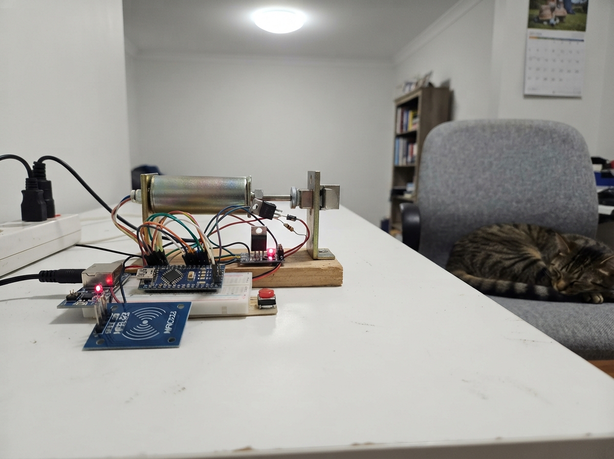
This RFID door lock system uses an ESP32 microcontroller to control a solenoid lock via RFID card authentication. The system includes tamper detection, a reed switch to sense door position, and an enrollment mode for adding new access cards. Builders will receive a complete wiring diagram showing how to safely interface the 12V solenoid through a MOSFET driver, connect the MFRC522 RFID reader with proper noise filtering, and integrate all sensors and indicators.
The guide covers power supply setup with the buck converter, assembly of the control circuit with protection diodes and fuses, and step-by-step testing procedures before installation. The included firmware handles card enrollment, access logging, lockout after failed attempts, and real-time feedback through LEDs and a buzzer. This is a practical project for makers wanting to add smart access control to a door or cabinet.
Wiring diagram

Gather all the parts
Assemble it in 6 steps
1. Verify the 12 V lock parts first
Read the label on the solenoid and confirm it says 12 V. Measure the solenoid current if possible, then choose an adapter, fuse, wire, diode, and MOSFET cooling that can safely handle that current. Do not continue if the solenoid says 24 V; a 24 V coil needs a complete 24 V power path.
- Confirm the IRLZ44N leg order from the datasheet for your exact package before soldering.
- The fuse value must be chosen from the measured coil current and its brief starting surge.
- Never connect 24 V to this 12 V design — it can overheat or destroy the lock coil and electronics.
- Do not treat a 12 V 2 A adapter as automatically sufficient; the coil rating decides this.
2. Set the converter to exactly 5 V
Connect only the 12 V adapter to the converter input through the inline fuse: adapter positive to fuse IN, fuse OUT to converter VIN+, and adapter negative to converter VIN−. Use a multimeter to adjust VOUT+ and VOUT− to 5.0 V, then disconnect power. Connect VOUT+ to ESP32 VIN/5V (power) and VOUT− to ESP32 GND (ground).
- Mark the adjusted converter so it is not accidentally turned later.
- Use either the external 5 V supply or USB during normal operation, not both at once unless your exact board has verified power protection.
- Do not connect an unadjusted converter to the ESP32 — excess voltage can permanently damage it.
- Never connect the fused 12 V wire directly to ESP32 VIN, 5V, 3V3, or any GPIO.
3. Wire the solenoid and MOSFET switch
Connect fuse OUT to the solenoid red VCC lead (lock power). Connect solenoid black GND lead to IRLZ44N DRAIN (switched return). Connect IRLZ44N SOURCE to the common GND line (ground). Connect GPIO27 through the 220 Ω gate resistor to IRLZ44N GATE (control). Connect the 10 kΩ gate pulldown from GATE to GND (keeps the lock off during startup). Put the flyback diode directly across the solenoid: striped Cathode to its red positive lead (protection), unstriped Anode to its black lead/MOSFET DRAIN (protection).
- Keep the high-current solenoid wires short and use screw terminals or soldered joints.
- With the usual IRLZ44N TO-220 view facing the flat marked side with legs down, pins are often Gate–Drain–Source, but verify your specific part.
- The diode stripe must face the solenoid red positive wire — reversing it creates a short circuit when power is applied.
- Keep fingers away from the moving lock pin; it can pinch during testing.
4. Connect the RFID reader and its noise filters
Connect RC522 VCC to ESP32 3V3 (power) and RC522 GND to ESP32 GND (ground). Connect SCK to GPIO18 (data), MOSI to GPIO23 (data), MISO to GPIO19 (data), SDA/SS to GPIO4 (reader-select signal), and RST to GPIO22 (reset). Place both capacitors close to the reader: the 100 nF capacitor between RC522 VCC and GND (noise filter), and the 10 µF capacitor positive lead to VCC with its striped negative lead to GND (power smoothing).
- Use short, secure reader wires; loose long wires often prevent cards from reading.
- The RC522 pin printed SDA is its select wire in this project, not an I2C connection.
- Do not connect RC522 VCC to 5 V — use only ESP32 3V3 or the reader can be damaged.
- Make sure the 10 µF capacitor's positive and striped negative leads are not swapped — reversed electrolytic capacitors can fail.
5. Add the protected controls and indicators
Mount the enrollment button inside the locked enclosure. Connect its SIGNAL to GPIO25 (service signal) and its GND pin to GND (ground). Connect the door reed switch NC to GPIO26 (door signal) and COM to GND (ground); mount its magnet so the contact is closed while the door is shut. Connect tamper-switch NC to GPIO13 (tamper signal) and COM to GND (ground); arrange it so opening the enclosure releases the switch. Connect the internal exit button SIGNAL to GPIO16 (exit signal) and GND to GND (ground). Connect GPIO32 through the green LED 220 Ω resistor to the green LED long leg, then its short leg to GND (authorized light). Connect GPIO33 through the red LED 220 Ω resistor to the red LED long leg, then its short leg to GND (warning light). Connect the low-current 3.3 V active piezo buzzer + to GPIO14 and − to GND (sound).
- A four-leg pushbutton needs one leg from each opposite side; two legs on one side are already connected.
- Mount the exit button on the safe side of the door and provide a mechanical way out as required by your location.
- Each LED needs its own 220 Ω resistor — connecting an LED directly to a GPIO can damage the LED or ESP32.
- Use only the specified low-current active piezo buzzer directly on GPIO14; a larger buzzer requires its own transistor driver.
6. Test safely before fitting the door
First power the ESP32 from USB only with the solenoid supply unplugged. Press Deploy, then check that the reader sees cards, the lights and buzzer respond, and the door and tamper switches change state. Next unplug USB, apply the adjusted external power, and bench-test short unlocks before mounting the solenoid in the door. Hold the hidden service button for eight seconds, scan each allowed card, then test unknown-card denial and the five-failed-scan 30-second lockout.
- The firmware saves up to four prototype cards and only writes its saved list when you enroll a card.
- After an authorized unlock, the controller relocks when the door closes after opening, or after five seconds if it never opens.
- Do not make a permanent installation on a solderless breadboard; use a perfboard or PCB, insulated terminals, strain relief, and an enclosure.
- This RC522 design compares card UIDs, which can be copied; it is for learning and small prototypes, not high-security access control.
Review all connections
1. Connections between "power_supply_1" and "ESP32"
2. Connections between "inline_fuse_1" and "ESP32"
3. Connections between "buck_5v_1" and "ESP32"
4. Connections between "solenoid_1" and "ESP32"
5. Connections between "flyback_diode_1" and "ESP32"
6. Connections between "gate_resistor_1" and "ESP32"
7. Connections between "gate_pulldown_1" and "ESP32"
8. Connections between "rc522_1" and "ESP32"
9. Connections between "enroll_button_1" and "ESP32"
10. Connections between "door_reed_1" and "ESP32"
11. Connections between "tamper_switch_1" and "ESP32"
12. Connections between "exit_button_1" and "ESP32"
13. Connections between "green_led_resistor_1" and "ESP32"
14. Connections between "green_led_1" and "ESP32"
15. Connections between "red_led_resistor_1" and "ESP32"
16. Connections between "red_led_1" and "ESP32"
17. Connections between "buzzer_1" and "ESP32"
18. Connections between "decoupling_100nf_1" and "ESP32"
19. Connections between "decoupling_10uf_1" and "ESP32"
Deploy the firmware
#include <Arduino.h>
#include <SPI.h>
#include <MFRC522.h>
#include <Preferences.h>


// Forward declarations
bool doorIsOpen();
bool enclosureIsOpen();
bool lockoutActive();
void buzz(unsigned long durationMs);
void setIndicators(bool green, bool red);
void lockDoor();
void unlockDoor(const char *reason);
void denyAccess(const char *reason);
void saveCards();
void loadCards();
int findCard(const uint8_t *uid, uint8_t length);
bool readCardUid(uint8_t *uid, uint8_t &uidLength);
void enterEnrollmentMode();
void addCard(const uint8_t *uid, uint8_t uidLength);
void updateEnrollmentButton();

constexpr uint8_t RC522_SS_PIN = 4;
constexpr uint8_t RC522_RST_PIN = 22;
constexpr uint8_t RC522_SCK_PIN = 18;
constexpr uint8_t RC522_MISO_PIN = 19;
constexpr uint8_t RC522_MOSI_PIN = 23;
constexpr uint8_t LOCK_PIN = 27;
constexpr uint8_t ENROLL_BUTTON_PIN = 25;
constexpr uint8_t DOOR_REED_PIN = 26;
constexpr uint8_t TAMPER_PIN = 13;
constexpr uint8_t EXIT_BUTTON_PIN = 16;
constexpr uint8_t GREEN_LED_PIN = 32;
constexpr uint8_t RED_LED_PIN = 33;
constexpr uint8_t BUZZER_PIN = 14;

constexpr unsigned long UNLOCK_TIME_MS = 5000;
constexpr unsigned long ENROLL_HOLD_MS = 8000;
constexpr unsigned long ENROLL_TIMEOUT_MS = 30000;
constexpr unsigned long LOCKOUT_TIME_MS = 30000;
constexpr unsigned long CARD_COOLDOWN_MS = 1000;
constexpr uint8_t MAX_CARDS = 4;
constexpr uint8_t MAX_UID_BYTES = 10;
constexpr uint8_t FAILED_ATTEMPTS_BEFORE_LOCKOUT = 5;

MFRC522 rfid(RC522_SS_PIN, RC522_RST_PIN);
Preferences preferences;
uint8_t authorizedUids[MAX_CARDS][MAX_UID_BYTES] = {};
uint8_t authorizedLengths[MAX_CARDS] = {};
uint8_t authorizedCount = 0;

bool unlocked = false;
bool doorOpenedDuringUnlock = false;
bool enrollmentMode = false;
bool enrollButtonWasDown = false;
unsigned long unlockStartedAt = 0;
unsigned long enrollmentStartedAt = 0;
unsigned long enrollButtonDownAt = 0;
unsigned long lockoutStartedAt = 0;
unsigned long lastCardAt = 0;
uint8_t failedAttempts = 0;

bool doorIsOpen() {
  return digitalRead(DOOR_REED_PIN) == HIGH;
}

bool enclosureIsOpen() {
  return digitalRead(TAMPER_PIN) == HIGH;
}

bool lockoutActive() {
  return lockoutStartedAt != 0 && millis() - lockoutStartedAt < LOCKOUT_TIME_MS;
}

void buzz(unsigned long durationMs) {
  digitalWrite(BUZZER_PIN, HIGH);
  delay(durationMs);
  digitalWrite(BUZZER_PIN, LOW);
}

void setIndicators(bool green, bool red) {
  digitalWrite(GREEN_LED_PIN, green ? HIGH : LOW);
  digitalWrite(RED_LED_PIN, red ? HIGH : LOW);
}

void lockDoor() {
  digitalWrite(LOCK_PIN, LOW);
  unlocked = false;
  doorOpenedDuringUnlock = false;
  setIndicators(false, enclosureIsOpen() || lockoutActive());
  Serial.println("Lock engaged.");
}

void unlockDoor(const char *reason) {
  digitalWrite(LOCK_PIN, HIGH);
  unlocked = true;
  doorOpenedDuringUnlock = false;
  unlockStartedAt = millis();
  setIndicators(true, false);
  Serial.print("Door unlocked: ");
  Serial.println(reason);
  buzz(80);
}

void denyAccess(const char *reason) {
  setIndicators(false, true);
  Serial.print("Access denied: ");
  Serial.println(reason);
  buzz(250);
}

void saveCards() {
  preferences.putUChar("count", authorizedCount);
  preferences.putBytes("uids", authorizedUids, sizeof(authorizedUids));
  preferences.putBytes("lens", authorizedLengths, sizeof(authorizedLengths));
}

void loadCards() {
  authorizedCount = preferences.getUChar("count", 0);
  if (authorizedCount > MAX_CARDS) {
    authorizedCount = 0;
  }
  preferences.getBytes("uids", authorizedUids, sizeof(authorizedUids));
  preferences.getBytes("lens", authorizedLengths, sizeof(authorizedLengths));
  for (uint8_t i = 0; i < authorizedCount; ++i) {
    if (authorizedLengths[i] == 0 || authorizedLengths[i] > MAX_UID_BYTES) {
      authorizedCount = 0;
      break;
    }
  }
}

int findCard(const uint8_t *uid, uint8_t length) {
  for (uint8_t card = 0; card < authorizedCount; ++card) {
    if (authorizedLengths[card] != length) continue;
    bool match = true;
    for (uint8_t i = 0; i < length; ++i) {
      if (authorizedUids[card][i] != uid[i]) {
        match = false;
        break;
      }
    }
    if (match) return card;
  }
  return -1;
}

bool readCardUid(uint8_t *uid, uint8_t &uidLength) {
  if (!rfid.PICC_IsNewCardPresent() || !rfid.PICC_ReadCardSerial()) {
    return false;
  }
  uidLength = rfid.uid.size;
  if (uidLength > MAX_UID_BYTES) uidLength = MAX_UID_BYTES;
  for (uint8_t i = 0; i < uidLength; ++i) uid[i] = rfid.uid.uidByte[i];
  rfid.PICC_HaltA();
  rfid.PCD_StopCrypto1();
  return true;
}

void enterEnrollmentMode() {
  enrollmentMode = true;
  enrollmentStartedAt = millis();
  setIndicators(true, false);
  Serial.println("Enrollment mode is active for 30 seconds. Scan a card to add it.");
  buzz(70);
  delay(80);
  buzz(70);
}

void addCard(const uint8_t *uid, uint8_t uidLength) {
  if (findCard(uid, uidLength) >= 0) {
    Serial.println("That card is already authorized.");
    buzz(80);
  } else if (authorizedCount >= MAX_CARDS) {
    Serial.println("Card list is full. This prototype stores four cards.");
    denyAccess("card list full");
  } else {
    for (uint8_t i = 0; i < uidLength; ++i) authorizedUids[authorizedCount][i] = uid[i];
    authorizedLengths[authorizedCount] = uidLength;
    authorizedCount++;
    saveCards();
    Serial.println("Card saved.");
    buzz(80);
    delay(80);
    buzz(80);
  }
  enrollmentMode = false;
  setIndicators(false, enclosureIsOpen());
}

void updateEnrollmentButton() {
  bool pressed = digitalRead(ENROLL_BUTTON_PIN) == LOW;
  if (pressed && !enrollButtonWasDown) {
    enrollButtonDownAt = millis();
  }
  if (pressed && !enrollmentMode && millis() - enrollButtonDownAt >= ENROLL_HOLD_MS) {
    enterEnrollmentMode();
  }
  enrollButtonWasDown = pressed;
}

void setup() {
  pinMode(LOCK_PIN, OUTPUT);
  digitalWrite(LOCK_PIN, LOW);
  pinMode(GREEN_LED_PIN, OUTPUT);
  pinMode(RED_LED_PIN, OUTPUT);
  pinMode(BUZZER_PIN, OUTPUT);
  digitalWrite(BUZZER_PIN, LOW);
  pinMode(ENROLL_BUTTON_PIN, INPUT_PULLUP);
  pinMode(DOOR_REED_PIN, INPUT_PULLUP);
  pinMode(TAMPER_PIN, INPUT_PULLUP);
  pinMode(EXIT_BUTTON_PIN, INPUT_PULLUP);
  setIndicators(false, false);

  Serial.begin(115200);
  preferences.begin("doorlock", false);
  loadCards();
  SPI.begin(RC522_SCK_PIN, RC522_MISO_PIN, RC522_MOSI_PIN, RC522_SS_PIN);
  rfid.PCD_Init();
  lockDoor();
  Serial.println("RFID door-lock controller ready.");
  Serial.println("UID matching is suitable only for a prototype; it is not high-security card authentication.");
  if (authorizedCount == 0) {
    Serial.println("No cards saved. Hold the hidden service button for 8 seconds, then scan a card.");
  }
}

void loop() {
  updateEnrollmentButton();

  if (enclosureIsOpen() && !unlocked) {
    setIndicators(false, true);
  }

  if (lockoutStartedAt != 0 && !lockoutActive()) {
    lockoutStartedAt = 0;
    failedAttempts = 0;
    setIndicators(false, enclosureIsOpen());
    Serial.println("Lockout ended.");
  }

  if (enrollmentMode && millis() - enrollmentStartedAt >= ENROLL_TIMEOUT_MS) {
    enrollmentMode = false;
    setIndicators(false, enclosureIsOpen());
    Serial.println("Enrollment timed out.");
  }

  if (unlocked) {
    if (doorIsOpen()) doorOpenedDuringUnlock = true;
    if ((doorOpenedDuringUnlock && !doorIsOpen()) || millis() - unlockStartedAt >= UNLOCK_TIME_MS) {
      lockDoor();
    }
  }

  if (!unlocked && digitalRead(EXIT_BUTTON_PIN) == LOW) {
    unlockDoor("inside exit button");
    delay(250);
    return;
  }

  uint8_t uid[MAX_UID_BYTES] = {};
  uint8_t uidLength = 0;
  if (!readCardUid(uid, uidLength)) return;
  if (millis() - lastCardAt < CARD_COOLDOWN_MS) return;
  lastCardAt = millis();

  if (enrollmentMode) {
    addCard(uid, uidLength);
    return;
  }
  if (enclosureIsOpen()) {
    denyAccess("enclosure tamper switch is open");
    return;
  }
  if (lockoutActive()) {
    denyAccess("temporary lockout is active");
    return;
  }
  if (findCard(uid, uidLength) >= 0) {
    failedAttempts = 0;
    unlockDoor("authorized card");
  } else {
    failedAttempts++;
    denyAccess("unknown card");
    if (failedAttempts >= FAILED_ATTEMPTS_BEFORE_LOCKOUT) {
      lockoutStartedAt = millis();
      Serial.println("Five failed scans: locked out for 30 seconds.");
    }
  }
}
Remix this project
Make it yours in one click
Open a full copy of this project in your own Schematik workspace — diagram, code, parts, and assembly steps included. Swap the sensor, add features, or redesign the whole thing with AI. The author's original stays untouched.